


NE555 Pin Configuration: A Clear 8-Pin Timer Guide

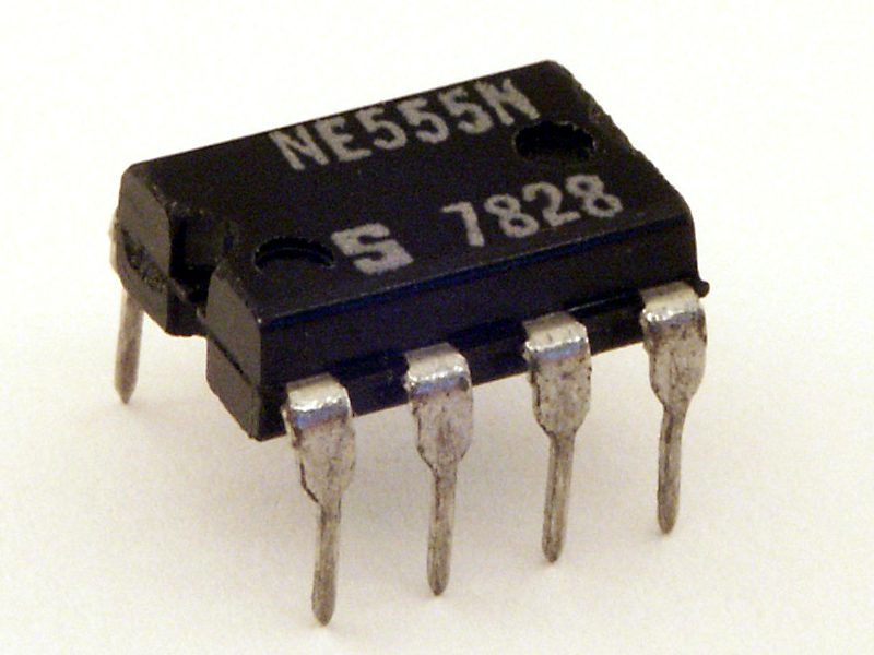
The NE555 pin configuration is straightforward once you distinguish trigger, threshold, reset and discharge. Those names describe different roles; joining the wrong pair can turn a working timer into a permanently high or low output. This guide covers the familiar 8-pin device and uses the Texas Instruments datasheet as the reference.
Orient the package before counting

Use the notch or pin-one marker and the datasheet’s top-view drawing for the exact package. Do not read a bottom-view sketch as a top view. An 8-pin DIP fits a solderless breadboard, while an SOIC device needs an appropriate adapter. The IC marking and package drawing matter more than a generic picture of a 555 circuit.
Keep the eight functions separate
| Pin | Name | Function in a basic circuit |
|---|---|---|
| 1 | GND | Supply return |
| 2 | TRIG | Starts or sets timing action when driven below its trigger level |
| 3 | OUT | Timer output signal |
| 4 | RESET | Active-low reset; hold high when unused |
| 5 | CONT | Control-voltage input |
| 6 | THRES | Senses the upper timing threshold |
| 7 | DISCH | Discharges the timing capacitor through the internal path |
| 8 | VCC | Positive supply within the device specification |
Trigger and threshold are comparator inputs, not power pins. Discharge is not a second copy of the output. Use the functional block diagram to understand why a timing capacitor can be connected to threshold and discharge in one circuit but arranged differently in another.
Choose a supply for the actual timer variant
The bipolar NE555 is not interchangeable with every low-voltage CMOS 555 implementation. Follow the recommended operating conditions for the exact part. A regulated 5 V bench supply is a practical starting point for many basic NE555 demonstrations, but do not assume a 3.3 V microcontroller rail is suitable for every NE555 device. Add local supply decoupling as recommended in the application circuit.
Prevent unwanted reset behavior
RESET is active low. If it is not used as a control input, the manufacturer recommends holding it at VCC rather than leaving it floating. A floating reset line can make timing appear unpredictable. When using reset intentionally, verify that the controlling circuit provides valid logic levels and does not exceed the timer’s input limits.
Understand trigger and threshold
With the conventional internal reference arrangement, trigger action occurs near one-third of the supply and threshold action near two-thirds. These are nominal functional levels, not a promise of exact measurement accuracy for every part and condition. The control-voltage pin can affect those reference levels, which is why its recommended connection or bypass capacitor should not be ignored.
Treat the output as a signal with limits
A timer output is not an unlimited power source. Use a resistor with an LED, and use an appropriate driver stage and protection for inductive or higher-current loads. Do not connect a motor or relay coil solely because a headline output-current figure looks large. Read output voltage, current and thermal conditions together. Keep beginner experiments limited to low-voltage, current-limited loads.Newest in the store


Inspect the timing network methodically
Check capacitor polarity, resistor values, breadboard rail breaks and the ground reference with power removed. A monostable and an astable use different timing connections. Start from one complete manufacturer application circuit and verify each net rather than mixing parts of several internet diagrams. If a pin voltage is unexpected, record the supply and pin readings before moving wires.
Epro parts and availability
These are relevant Epro listings, not independent authenticity or performance certifications. Prices below were checked on 19 October 2026; they are a dated snapshot rather than a historical price implied by this article’s publication date. Confirm the exact variant, included accessories, stock and current checkout price before ordering.
| Listing | Checked price | Stock at check |
|---|---|---|
| 555 Timer IC NE555 LM555 Timer IC | PKR 14 | In stock |
Frequently asked questions
Are trigger and threshold the same input?
No. They perform different comparator functions, even though an astable circuit commonly joins them at a timing-capacitor node.
Can I leave RESET open?
Do not leave it floating. Follow the datasheet; hold it high when reset control is not used.
Related Epro guides
Technical references and verification
The guidance above is based on the manufacturer documentation linked here and the listed product information. Example procedures and sketches are provided for a controlled low-voltage bench setup; no independent hands-on test of your particular board or adapter is claimed. Check the markings and documentation for your actual revision.