


TCS34725 with Arduino: A Repeatable Color-Sampling Setup

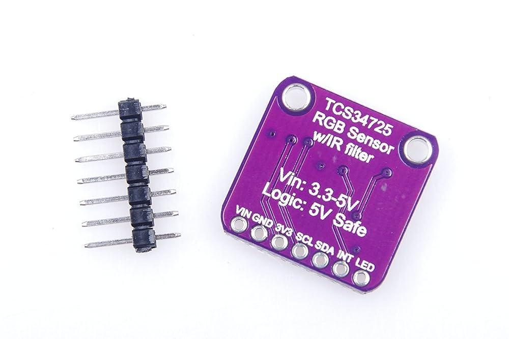
Using a TCS34725 with Arduino is most useful when the wiring and sample conditions are documented together. This procedure establishes a repeatable RGBC measurement before adding color names or a sorting mechanism. It uses the maintained Adafruit library examples as the software starting point, not a claim that every third-party breakout matches Adafruit hardware.
Choose a supported electrical arrangement

Check the supply and logic levels of both the microcontroller and the actual breakout. A 5 V Uno requires an interface arrangement that is explicitly safe for the sensor; a 3.3 V board still needs the correct supply and pull-up configuration. Follow the breakout schematic. Never infer level shifting solely from a regulator being present.
Connect the correct I2C pins
With power disconnected, connect documented sensor supply, common ground, SDA and SCL. On a classic Uno the I2C signals are SDA/A4 and SCL/A5; other boards differ. Keep leads short for the first test and connect only one 0x29 device. If an LED-control pin exists, consult the actual module circuit before driving it.
Install and run the library baseline
Install Adafruit TCS34725 and its listed dependencies through Arduino IDE Library Manager. Open the library’s basic sensor example and check initialization before changing its code. The repository documents the driver and example files. Record the selected board, library version and gain/integration settings so later comparisons are not made against an unknown baseline.
Log raw channels before assigning labels
Use the example’s getRawData operation to record R, G, B and clear counts. Begin with a fixed sample holder and steady light. Collect multiple readings for a dark reference, a white reference and several colored targets. Keep gain and integration constant during this initial comparison. Values near the setting-dependent saturation limit require less gain, shorter integration or reduced illumination.
Use guarded normalization only when appropriate
A ratio such as R/C can be useful for a restricted experiment, but only when C is safely above the noise floor and none of the channels is saturated. Check for zero before division. Such ratios are not universal color coordinates. If changing lamp type changes the classifications, improve the measurement conditions rather than simply adding more decimal places.
Test repeatability separately from recognition
Remove and replace the same sample several times and observe the spread of readings. Then test samples not used to choose thresholds. Record failures and ambiguous cases rather than forcing every observation into a confident color name. This is a learning setup, not a validated industrial sorter; moving machinery also requires separate guarding and control design.
Newest in the store


Diagnose initialization and unstable readings
A failed begin operation calls for supply, address and SDA/SCL checks. A responding device with inconsistent colors calls for checking illumination, distance, integration and saturation. Do not repeatedly replace a functioning library when the main variation comes from a hand-held target or changing sunlight. Change one condition at a time and keep a short test log.
Relevant Epro listing
Product information and prices were checked on 19 October 2026. This is a current snapshot, not a historical price associated with the publication timestamp. Stock, accessories and checkout prices can change. Listing claims are not independent performance or authenticity certifications.
| Product | Checked price | Stock |
|---|---|---|
| TCS34725 Digital Color Detection Sensor – RGB & Light Sensing Module | PKR 970 | In stock |
Frequently asked questions
Why not identify red by the largest raw channel alone?
Illumination, target reflectance and channel response affect the counts. A simple rule needs testing against the actual samples and conditions.
Is an I2C scanner enough to prove correct readings?
No. It checks an address response, not gain, integration, optical conditions or measurement accuracy.
Related Epro reading
Review breadboard connections before assembling a prototype. For controller expansion, the Mega 2560 pin guide explains why pin names and electrical limits must be checked together.
Technical references and test limitations
This guide uses the documentation linked below. The procedures are for a controlled, low-voltage learning setup; no independent hands-on test of the particular seller board is claimed. Record the actual part markings, wiring and firmware version before drawing conclusions from a test.