


ULN2803 Pinout: Eight Low-Side Drivers and the COM Pin

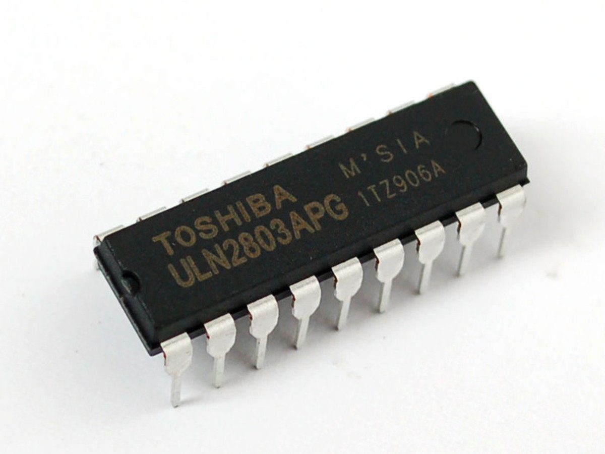
The ULN2803A contains eight Darlington sink drivers with common emitters and integrated suppression diodes. It can simplify several low-side load controls, but the COM pin is not a normal logic-supply pin and eight channel ratings cannot simply be added into a guaranteed package current.
Identify the exact family member

ULN2801A, ULN2802A, ULN2803A and ULN2804A have different input arrangements. The referenced ST documentation describes the ULN2803A with input resistors intended for five-volt TTL/CMOS use. Do not assume every similarly numbered array has identical input behavior. Confirm the supplied marking, package and manufacturer before choosing a host interface.
Map inputs and outputs from the drawing
For the common eighteen-pin arrangement, inputs 1–8 are on pins 1–8, common emitter is pin 9 and COM is pin 10. The corresponding outputs run in reverse physical order, from output 8 on pin 11 through output 1 on pin 18. Verify the package view and channel pairing rather than connecting equal pin numbers across the package.
Understand sink operation
A load normally connects from its supported positive supply to an output collector. An asserted compatible input makes the channel sink current toward the common emitter return. The chip does not provide a high-side positive supply or a push-pull output. Each LED still needs a suitable resistor; the array does not regulate every load to a chosen current.
Connect COM according to the load protection design
COM joins the cathodes of the internal clamp diodes. For a conventional supported inductive-load circuit it connects to the appropriate positive load-supply rail so the diodes provide a flyback path. It is not the emitter ground and not an input-logic power pin. Follow the complete manufacturer application and check voltage/transient limits.
Calculate package heat and simultaneous loading
Darlington outputs have an on-state voltage drop, which dissipates power at the load current. Check how many channels operate together, duty cycle, ambient conditions and package thermal limits. A per-channel maximum is not permission to run all eight at that value indefinitely. Supply and PCB traces also need an appropriate current budget.
Check host drive and inactive behavior
Input current and switching thresholds must be compatible with the controller at the intended output current. Do not assume a three-volt GPIO works at every advertised load condition simply because a five-volt example exists. Use defined startup states so loads are not enabled by floating signals. Test with low-current resistive loads before considering coils or other consequential outputs.Newest in the store


Relevant Epro listing
Product information and prices were checked on 19 October 2026. This is a current snapshot, not a historical price associated with the publication timestamp. Stock, accessories and checkout prices can change. Listing claims are not independent performance or authenticity certifications.
| Product | Checked price | Stock |
|---|---|---|
| ULN2803 IC in Pakistan | PKR 50 | In stock |
Frequently asked questions
Is COM the ground pin?
No. Common emitter is the return; COM is the shared clamp-diode cathode connection.
Can all eight channels run at the single-channel maximum?
Do not assume that. Total dissipation, duty cycle, temperature and package limits must be checked.
Related Epro reading
Review breadboard connections before assembling a prototype. For controller expansion, the Mega 2560 pin guide explains why pin names and electrical limits must be checked together.
Technical references and test limitations
This guide uses the documentation linked below. The procedures are for a controlled, low-voltage learning setup; no independent hands-on test of the particular seller board is claimed. Record the actual part markings, wiring and firmware version before drawing conclusions from a test.