


A3144 Arduino: Pull-Up Wiring and One-Event-Per-Pass Checks

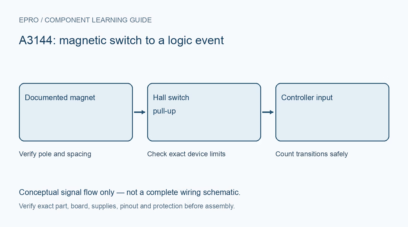
An A3144 Arduino test should first identify a stable idle state and a repeatable magnet-detection transition. Use a hand-moved magnet and a compatible pull-up before attempting rotation counting. The exact supplied device may differ from the discontinued original, so matching documentation is essential.
Identify pins and operating conditions
Use the actual manufacturer’s package drawing, not an assumed flat-face pin order. Check supply requirements and output type. The original Allegro reference describes an open-collector switch, but a module may add an LED, resistor or comparator that changes its external behavior. Record whether testing a bare part or a carrier.
Choose a safe logic pull-up
Connect the sensor output through an appropriate pull-up arrangement to a voltage safe for the selected Arduino input, provided the exact device permits it. Confirm whether the board already has a pull-up tied to its supply. Do not connect an unknown 5 V-pulled module output directly to a 3.3 V-only pin. Share the intended signal reference.
Log the raw state before counting
With a current-limited low-voltage setup and the sensor powered correctly, print the raw input state at a moderate rate. Present the documented magnet pole and withdraw it, keeping orientation repeatable. Try the opposite pole only as a controlled identification check, not as proof every Hall switch has the same polarity or latch behavior.
Count transitions, not every sampled active level
Decide whether one approach or one release defines the event. Increment on that transition rather than on every loop while the magnet remains near the sensor. Confirm that one deliberate pass produces one event. Apply an appropriate noise or minimum-interval policy without hiding real events at the intended maximum rate.
Separate pulse rate from shaft speed
A later rotation project must know how many valid detection events occur per revolution. Dividing pulse rate by an assumed one magnet per revolution can give the wrong speed if several magnets, edges or false events are counted. Define the measurement window or interval method, time units and zero-speed timeout explicitly.
Validate mechanics before any powered rotation
Secure the magnet and guard moving parts before using a motorized test. Verify timing limits, signal quality and event handling at the required rate with appropriate equipment. A slow hand test does not establish high-speed performance or protection functionality. Keep the initial demonstration away from vehicle control, hazardous machinery and any sole safety interlock.Newest in the store


Availability and illustration note
No matching product was found in the checked Epro catalog for this topic on 19 October 2026. This article therefore does not quote an Epro price or claim stock. The original illustration shows conceptual signal flow only, not a complete circuit or a photograph of a supplied product. Obtain a documented component or carrier with a known pinout and electrical specification.
Frequently asked questions
Why does one magnet pass produce many counts?
The application may count every active sample or respond to noise. Detect the intended edge and validate the signal.
Does one sensor pulse always equal one shaft revolution?
No. It depends on magnets, geometry, selected edges and the event definition.
Related Epro reading
Review breadboard connections before assembling a prototype. For controller expansion, the Mega 2560 pin guide explains why pin names and electrical limits must be checked together.
Technical references and test limitations
This guide uses the documentation linked below. The procedures are for a controlled, low-voltage learning setup; no independent hands-on test of the particular seller board is claimed. Record the actual part markings, wiring and firmware version before drawing conclusions from a test.