


INA226 Circuit: A Small DC Load and Calibration Read-Back Test

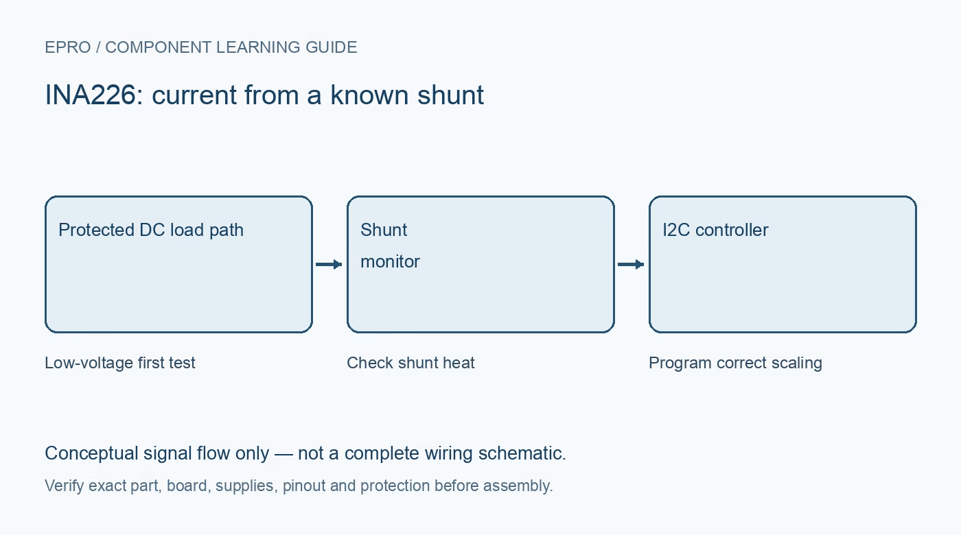
An INA226 circuit should first be checked with a small, known DC load on a current-limited low-voltage supply. Establish the actual shunt resistance and preserve raw voltage readings so wiring, register decoding and current calibration can be assessed independently.
Draw the complete load-current path
Identify supply positive, shunt input and output, load and return from the actual board schematic. The monitor’s logic supply is a separate requirement. Do not confuse a VCC header with the high-side current path or connect an unknown terminal based only on its position. Verify polarity and continuity with power removed.
Keep the test load controlled
Choose a documented low-power resistive load with suitable voltage and power ratings and use a current-limited supply. Check its approximate expected current and heating before connection. Keep the load path out of thin logic jumpers and controller power pins. The monitor is not an ammeter that can safely be placed across a supply without a load.
Check I2C levels and device identity
Confirm logic supply, pull-up voltage, common reference and address configuration. Read documented identification or configuration registers where supported by the selected driver. An acknowledged I2C address is only a communication check, not confirmation that the shunt terminals are wired correctly or that the measured current scale is correct.
Read raw bus and shunt values first
Use the documented byte order and signed handling for the differential shunt register. Compare polarity with the intended current direction and confirm bus voltage with a suitable meter. A reversed shunt can produce negative current without implying the device is broken. Investigate unexpected offsets or saturation before applying a numerical calibration factor.
Program and verify the actual scale
Follow the datasheet relation CAL = 0.00512 divided by the product of Current_LSB and shunt resistance, using amperes and ohms consistently. Confirm the result fits the register and that the current range remains within all device and shunt limits. Read back the configuration where appropriate; do not copy a calibration constant calculated for another board’s resistor.
Compare under stable conditions and restart once
Allow the selected conversion and averaging interval to complete, then compare against an appropriately connected reference instrument. Avoid changing the test circuit while interpreting the result. Record shunt value, settings, raw readings and units. Because configuration is volatile, verify the software restores it after a controlled power cycle before showing a current or power result as valid.Newest in the store


Availability and illustration note
No matching product was found in the checked Epro catalog for this topic on 19 October 2026. This article therefore does not quote an Epro price or claim stock. The original illustration shows conceptual signal flow only, not a complete circuit or a photograph of a supplied product. Obtain a documented component or carrier with a known pinout and electrical specification.
Frequently asked questions
Can the current terminals be connected directly across a supply?
No. A shunt path is not a safe load by itself. Wire the intended protected load circuit correctly.
Can a calibration value be copied from any INA226 example?
Only if the actual shunt and chosen current scale match and all operating limits are met. Calculate and verify them explicitly.
Related Epro reading
Review breadboard connections before assembling a prototype. For controller expansion, the Mega 2560 pin guide explains why pin names and electrical limits must be checked together.
Technical references and test limitations
This guide uses the documentation linked below. The procedures are for a controlled, low-voltage learning setup; no independent hands-on test of the particular seller board is claimed. Record the actual part markings, wiring and firmware version before drawing conclusions from a test.