


Si7021 Humidity Sensor: 7 Supply and Placement Checks

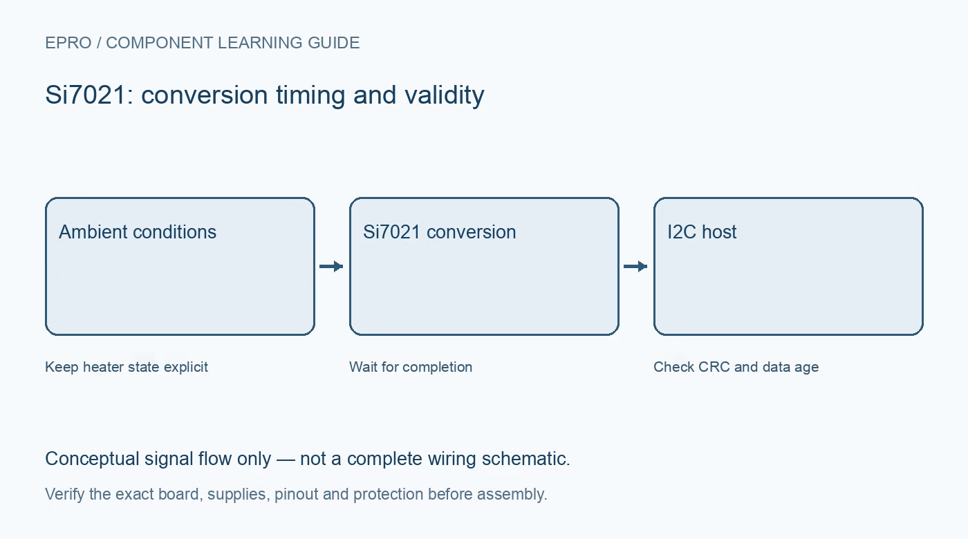
A Si7021 combines calibrated humidity and temperature sensing with an I2C interface. To select a useful module, separate the sensor IC’s operating limits from whatever a carrier adds, then consider how the finished assembly will exchange heat and air.
Confirm the exact part and protective option
The Si7021-A20 datasheet distinguishes grades and ordering options, including a protective cover. A cover on a sensing element does not certify an entire breakout, connector or enclosure for water exposure. Confirm the actual ordered part rather than treating every online photograph as the same assembly.
Respect the chip’s low-voltage supply
The referenced IC operates from 1.9 to 3.6 V. A board may add regulation and translation, but their presence must be documented. Verify both the board input and I2C high level. A regulator feeding the sensor does not, by itself, protect its data pins from an incompatible pull-up rail.
Budget for the fixed I2C address
The seven-bit base address is 0x40. Check other peripherals before assigning the same bus. Two fixed-address modules cannot be independently selected merely by constructing two software objects. Separate buses or a suitable multiplexer may be needed when monitoring multiple positions.
Compare accuracy within its stated conditions
The datasheet states humidity and temperature limits over specified ranges and grades. Do not apply the most attractive accuracy figure to all possible temperatures, aging conditions and enclosure designs. Display resolution is also not a guarantee of real-world accuracy at the installed location.
Place the sensor away from avoidable heat
Keep it away from regulators, illuminated displays and other local heat sources. The thermal path through the board influences the internal temperature sensor. Give air access to the sensing area and allow the completed assembly to settle before judging whether a reading represents the room.
Understand the internal heater
The heater can raise sensor temperature for special diagnostics and moisture-related procedures. It also changes local relative humidity and current consumption. Leave it disabled for an ordinary ambient baseline unless an explicitly designed measurement method calls for it, and track its state in the application.
Newest in the store


Require data-integrity and freshness handling
Choose a library that reports bus failures and supports the sensor’s documented integrity checks. Specify a maximum acceptable sample age before purchase. A readable display is not enough if it keeps showing yesterday’s temperature after communication stops. Include placement and maintenance in the system requirements, not just the sensor part number.
Frequently asked questions
Is a covered Si7021 module waterproof?
A sensing-element cover specification does not establish a waterproof rating for the complete board or installed enclosure.
Can the heater calibrate the sensor automatically?
Not by itself. Heating changes sensor conditions; it does not create a traceable humidity or temperature reference.
Availability and illustration note
No matching Epro product was returned by the catalog search on 19 October 2026. This learning guide does not assert stock, a selling price or compatibility of an unidentified substitute. The illustration is an original conceptual signal-flow diagram, not a product photograph or complete wiring schematic.
Related Epro reading
For a first bench setup, review breadboard connections and continuity checks and I2C voltage-level translation. These guides do not replace the exact module schematic.
Technical references and limitations
Source: Silicon Labs Si7021-A20 datasheet. Electrical limits apply to the named part, not automatically to every carrier board. This is a documentation-based learning workflow, not a claim of independent hardware testing, traceable calibration or safety certification.