


DS1302 RTC Module: Three-Wire Interface and Battery Safety

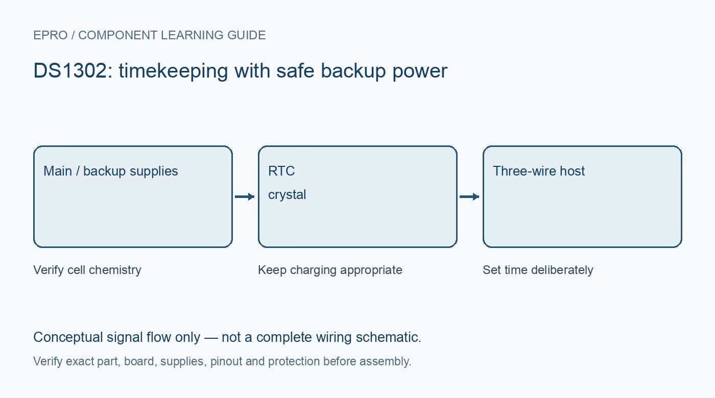
A DS1302 RTC module keeps calendar time through a three-wire synchronous interface and can use a backup energy source. Battery chemistry and charging configuration must be understood before fitting a cell. A coin-cell holder is not proof that every similarly sized rechargeable or non-rechargeable cell is appropriate.
Do not wire it like an I2C RTC
The DS1302 uses CE, a bidirectional I/O line and SCLK, rather than SDA/SCL I2C addressing. A DS1307 or DS3231 library and wiring diagram will not directly apply. The controller must follow the documented command format and data-direction timing. Labels such as CLK and DAT on a module describe this specific interface.
Inspect the backup circuit before installing a cell
The device has primary and backup supply connections plus a configurable trickle charger. Determine the actual carrier circuit and the recommended backup source. Never charge a primary lithium coin cell such as CR2032. Do not substitute a rechargeable cell merely because it fits; its voltage, chemistry and charging requirements must match the designed circuit.
Keep charging disabled unless properly designed
The datasheet states the IC powers up with trickle charging disabled and describes a specific enabling pattern. Existing firmware or added board components can affect the complete circuit, so verify actual configuration rather than relying only on the chip default. Leave charging disabled for a non-rechargeable backup arrangement and follow the documented carrier design.
Read clock-halt and write-protect states
The clock-halt bit can stop the oscillator, and write protection prevents changes. Their initial states require deliberate handling as documented. If time does not advance or a setting does not persist, inspect these controls before replacing the crystal or repeatedly setting the clock. Keep configuration changes explicit and recoverable.
Separate clock/calendar data from text formatting
Clock registers use binary-coded decimal and include 12/24-hour format handling. A suitable library should decode and validate them correctly. Decide whether the stored calendar represents UTC or a chosen local convention and document that decision. The RTC does not supply time-zone rules, network synchronization or a continuously corrected reference by itself.
Assess accuracy and application needs honestly
An external crystal and board layout influence timekeeping. A clock advancing on the serial monitor is not an accuracy qualification. Compare over a meaningful interval with a trustworthy time reference and record temperature and power conditions. For demanding timing requirements, choose hardware and a synchronization strategy specified for the needed performance.Newest in the store


Availability and illustration note
No matching product was found in the checked Epro catalog for this topic on 19 October 2026. This article therefore does not quote an Epro price or claim stock. The original illustration shows conceptual signal flow only, not a complete circuit or a photograph of a supplied product. Obtain a documented component or carrier with a known pinout and electrical specification.
Frequently asked questions
Can a CR2032 be used with trickle charging enabled?
No. Do not charge a primary CR2032. Verify the complete carrier and use a backup arrangement designed for the chosen chemistry.
Does DS1302 have an I2C address to scan?
No. It uses its documented three-wire synchronous interface, not the I2C address protocol.
Related Epro reading
Review breadboard connections before assembling a prototype. For controller expansion, the Mega 2560 pin guide explains why pin names and electrical limits must be checked together.
Technical references and test limitations
This guide uses the documentation linked below. The procedures are for a controlled, low-voltage learning setup; no independent hands-on test of the particular seller board is claimed. Record the actual part markings, wiring and firmware version before drawing conclusions from a test.