


MAX31865 Arduino: 7 Reference, Wiring and Fault Checks

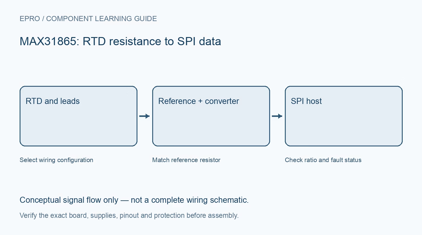
A useful MAX31865 Arduino test logs the resistance information and fault status as well as temperature. Start with one verified RTD module and a low-energy room-temperature setup. Do not make a heater or process controller the first test load for new measurement code.
Document the board and probe before power-up
Record the module revision, fitted reference-resistor value, probe nominal resistance and two-, three- or four-wire configuration. Verify any solder jumpers against that carrier’s schematic. Use continuity checks with power disconnected to identify same-end probe leads where appropriate; do not rely on colour conventions alone.
Wire a compatible SPI host
Identify supply, ground, chip select, SCLK, SDI and SDO. Module SDI receives host MOSI; module SDO feeds host MISO. A board-level regulator does not prove level translation. The IC itself uses 3.0 to 3.6 V supplies, and SPI operation must use the supported mode and acceptable clock rate.
Pass the real resistance parameters to the driver
Install a maintained library for MAX31865 and select the correct wiring mode. Set both nominal RTD resistance and the actual board reference resistance. A PT100 with an incorrect reference value can produce stable but wrong temperature, so stability alone is not an acceptance criterion.
Respect bias settling and conversion timing
A one-shot reading requires enabling bias, allowing the documented input network to settle and then completing conversion. The datasheet gives approximately 52 ms in 60 Hz filter mode and 62.5 ms in 50 Hz filter mode. A driver may manage this sequence, but inspect its behaviour before writing a fast polling loop.
Decode the resistance word before temperature
The RTD data combines a 15-bit conversion value with a fault indicator. After extracting the code correctly, resistance is code × reference resistance / 32768. Temperature conversion must use the selected platinum RTD characteristics. Avoid presenting a simple resistance-to-temperature shortcut as accurate across the whole probe range.
Read and report faults rather than hiding them
Check fault status before accepting a sample and distinguish bus errors from sensor-circuit faults. Log the raw code, configuration and fault flags when troubleshooting. Clear a latched status only through the documented procedure after addressing the cause, not on every loop simply to keep the display looking normal.
Newest in the store


Test a safe reference and recovery path
Use a suitable known resistor or verified room-temperature probe to compare expected resistance with the decoded ratio. Power down before changing connections. An intentional disconnected-probe test can demonstrate some fault handling, but it cannot certify detection of every possible cable break. Keep timestamps and mark failed or old readings explicitly.
Frequently asked questions
Which mains-rejection setting should I choose?
Choose the appropriate 50 or 60 Hz filter for the environment and respect its conversion timing. Filtering does not replace safe wiring or galvanic isolation.
Can I ignore faults if temperature is plausible?
No. A plausible number can accompany an invalid sensor configuration or some cable conditions. Inspect status and the whole measurement chain.
Availability and illustration note
The Epro MAX31865 listing was shown at PKR 1,500 and in stock when checked on 19 October 2026. This is a dated listing snapshot, not a historical price associated with this article’s publication timestamp. Confirm the fitted reference resistor, probe type and board jumpers before ordering. The illustration is an original conceptual signal-flow diagram, not a product photograph or complete wiring schematic.
Related Epro reading
For a first bench setup, review breadboard connections and continuity checks and I2C voltage-level translation. These guides do not replace the exact module schematic.
Technical references and limitations
Source: Analog Devices MAX31865 datasheet. Electrical limits apply to the named part, not automatically to every carrier board. This is a documentation-based learning workflow, not a claim of independent hardware testing, traceable calibration or safety certification.