


TSL2561 Light Sensor: 7 Lux and Integration Checks

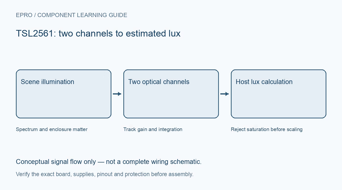
A TSL2561 converts two optical channels into digital readings from which software estimates illuminance. It is more informative than a simple light-dependent resistor, but buying a digital light sensor does not automatically create a calibrated lux meter.
Understand what the channels represent
Channel 0 responds to broadband light including infrared; channel 1 responds mainly to infrared. The lux estimate uses their relationship to approximate human visual response. One channel alone is not already a universal lux value, and subtracting channels is not a complete calibration method.
Check chip and carrier voltage requirements
The referenced sensor’s recommended supply range is 2.7 to 3.6 V. Some carriers may add regulation or level shifting; verify the exact board before connecting a 5 V host. Check the pull-up rail as carefully as the board’s power-input label.
Plan the selectable address
TSL2561 supports address choices including 0x29, 0x39 and 0x49 according to the address-pin connection. Check how the carrier exposes that choice and whether other devices already use the intended address. Document hardware selection rather than simply changing an address argument in software.
Match gain and integration to expected lighting
The device provides 1× and 16× gain and nominal integration intervals of 13.7, 101 and 402 ms. Longer integration can improve low-light measurement but increases latency and changes saturation behaviour. Select settings for both dim and bright conditions rather than copying a single indoor example.
Reject saturated observations
An over-range channel cannot support a trustworthy lux estimate. Software should recognize saturation for the active integration time, reduce sensitivity when appropriate, and wait for a complete measurement at the new setting. A saturated sensor is not evidence of exactly the maximum displayed lux.
Consider spectrum, angle and enclosure
Different lamps have different spectra; the empirical lux calculation is an approximation. Cover windows, tinted plastic, dust and mounting angle further change the response. Evaluate the final optical path and intended light sources instead of assuming the bare sensor’s characteristics survive any enclosure unchanged.
Newest in the store


Define the purpose before purchase
Automatic display dimming may tolerate relative readings that would be unsuitable for documenting workplace illuminance compliance. Record whether the project needs trends, thresholds or traceable absolute values. The sensor’s digital resolution and a library’s decimal formatting do not establish a calibrated instrument specification.
Frequently asked questions
Is channel 0 already a lux measurement?
No. The documented algorithm uses channel information plus gain, integration and package-dependent factors to estimate illuminance.
Will the longest integration always be best?
No. It trades response time and bright-light headroom against low-light sensitivity.
Availability and illustration note
No matching Epro product was returned by the catalog search on 19 October 2026. This learning guide does not assert stock, a selling price or compatibility of an unidentified substitute. The illustration is an original conceptual signal-flow diagram, not a product photograph or complete wiring schematic.
Related Epro reading
For a first bench setup, review breadboard connections and continuity checks and I2C voltage-level translation. These guides do not replace the exact module schematic.
Technical references and limitations
Source: TAOS TSL2560/TSL2561 datasheet. Electrical limits apply to the named part, not automatically to every carrier board. This is a documentation-based learning workflow, not a claim of independent hardware testing, traceable calibration or safety certification.