


LM75B Temperature Sensor: 7 Variant and Alert Checks

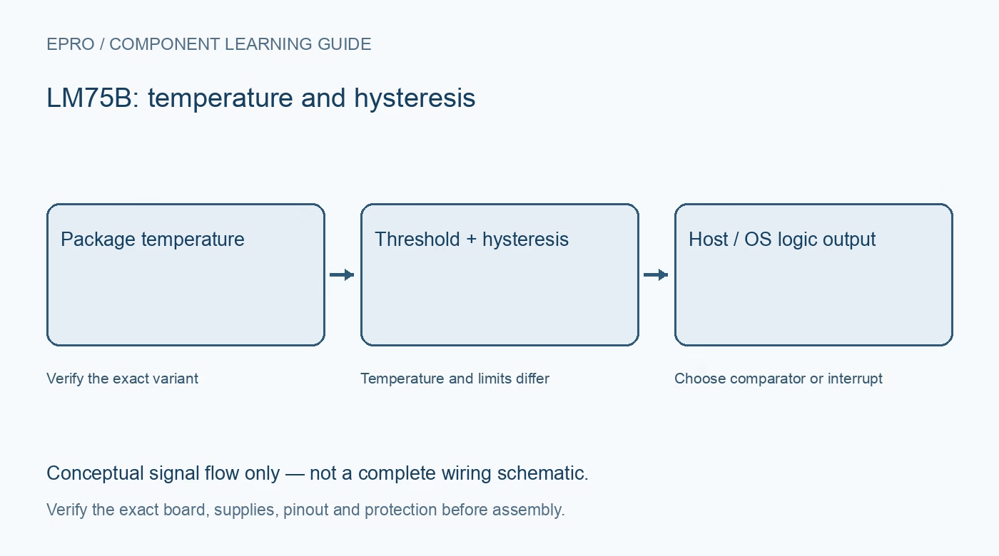
The LM75 family name is not enough to identify every register detail. This guide refers specifically to the NXP LM75B. Check the fitted manufacturer and suffix before applying its temperature resolution or alert behaviour to an older LM75 or a compatible replacement.
Identify the exact variant
Some family members and replacements use different resolutions or electrical limits. A listing that says only LM75 does not establish that the fitted part is an NXP LM75B. Read package markings and documentation before deciding which driver features and conversion format to enable.
Distinguish temperature and threshold steps
The LM75B temperature result is eleven-bit signed data with 0.125 degree Celsius resolution. Its overtemperature and hysteresis thresholds use nine-bit values with 0.5 degree steps. Selecting a fine display step cannot make the threshold registers accept equally fine changes.
Use guaranteed accuracy limits
The datasheet specifies maximum error of two degrees Celsius over minus 25 to 100 degrees, with a different limit across the full operating interval. Resolution does not replace those limits. A precise-looking display must not be advertised as a laboratory calibration result.
Plan address straps and conflicts
Three hardware address inputs permit addresses from 0x48 through 0x4F. That range is shared by other temperature devices. Check all connected modules before assigning an address, and verify that carrier solder bridges actually change the intended input levels.
Choose comparator or interrupt behaviour
Comparator mode tracks threshold crossings with hysteresis, while interrupt mode latches an event and uses register reads as part of its clearing behaviour. Pick the mode against the application state machine rather than assuming the output is always a direct too-hot indicator.
Keep OS electrically within its role
The open-drain overtemperature output needs a suitable pull-up and is a logic signal, not a fan or heater power source. Check polarity, fault queue and host input limits. Test with an input monitor before adding any separately engineered load-control stage.
Newest in the store


Design for stable thermal observations
Keep the sensor away from local heat sources when measuring air and allow the assembly to settle. A learning-module alert is not an independent certified safety cutoff. Use appropriate dedicated protection for equipment where a missed temperature event could cause injury or damage.
Frequently asked questions
Do all LM75-labelled devices use eleven-bit temperature data?
No. Confirm the exact manufacturer and variant; this guide targets NXP LM75B.
Can threshold settings use every displayed temperature step?
No. The LM75B threshold step is 0.5 degrees, distinct from the 0.125 degree temperature-result step.
Availability and illustration note
No matching Epro product was returned by the catalog search on 21 October 2026 UTC. This learning guide does not assert stock, a selling price or compatibility of an unidentified substitute. The illustration is an original conceptual signal-flow diagram, not a product photograph or complete wiring schematic.
Related Epro reading
For a first bench setup, review breadboard connections and continuity checks and I2C voltage-level translation. These guides do not replace the exact module schematic.
Technical references and limitations
Source: NXP LM75B datasheet. Electrical limits apply to the named part, not automatically to every carrier board. This is a documentation-based learning workflow, not a claim of independent hardware testing, traceable calibration or safety certification.