


MCP23017 Arduino: 7 Latch and Interrupt-Capture Checks

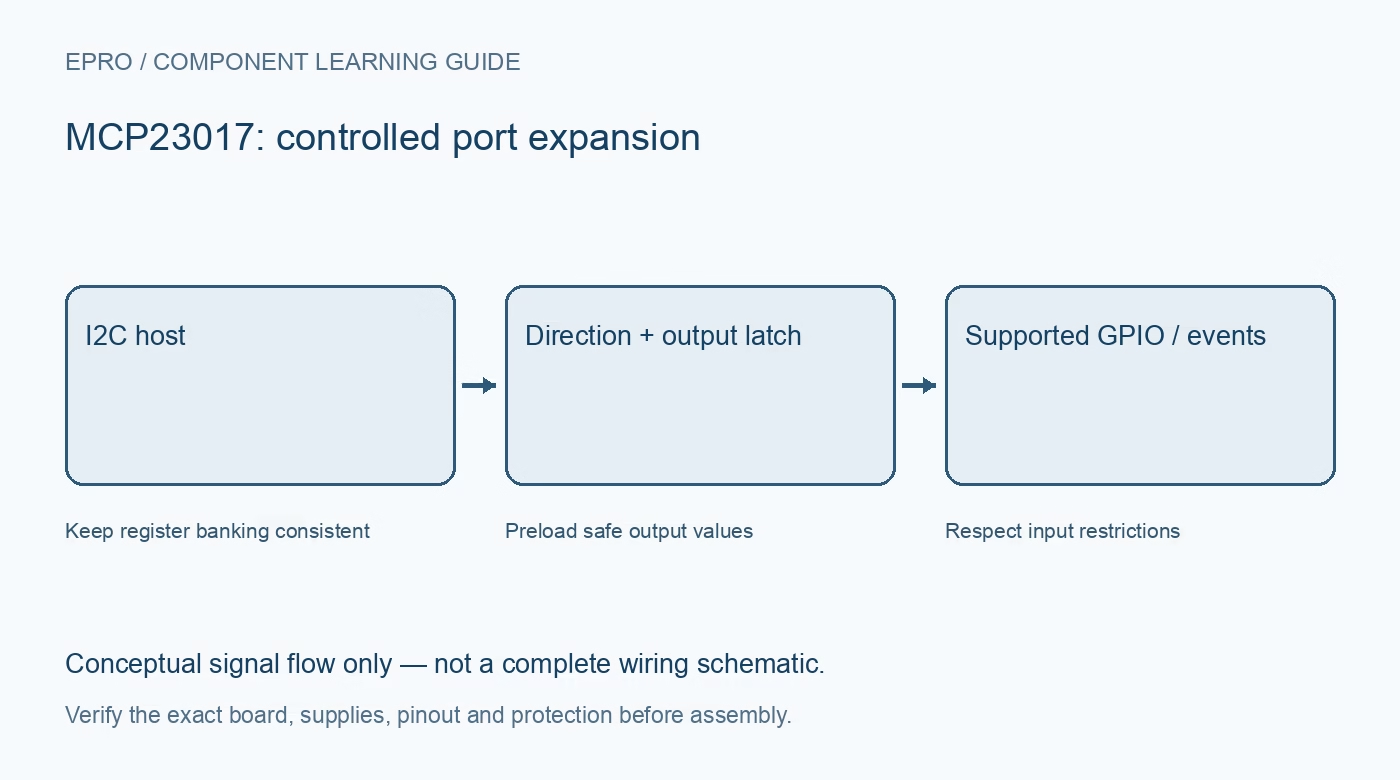
A dependable MCP23017 Arduino test begins with one button and one low-current indication, not a fully populated load board. Keep input allocation, stored output values and interrupt servicing explicit so a readable register is not mistaken for a correctly configured system.
Verify rails, reset and address wiring
Check supply compatibility, I2C pull-up voltage, common ground and address straps against the carrier schematic. Ensure reset has a defined inactive state. Power down before moving wires, and begin at a supported conservative bus speed with only the expander attached.
Choose supported button positions
Use a permitted input such as GPA0 rather than GPA7 or GPB7, which the referenced current MCP23017 documentation identifies as output-only. Enable a documented pull-up arrangement and connect the button only within the intended logic rails. Mechanical contacts still require suitable debounce handling.
Establish a known register map
Initialize through the correct MCP23017 driver and confirm its banking assumptions. Avoid mixing a library with raw address constants copied from another BANK mode. If settings appear to move unexpectedly, read configuration and reset status before repeatedly writing the whole register map.
Preload the latch before enabling an output
Set the intended safe output value in the latch before changing its supported pin to output, using APIs whose sequencing is understood. This reduces an avoidable transition from a retained or reset latch value. The downstream circuit should still have an independently safe reset state.
Preserve outputs through OLAT or a shadow
Do not build a read-modify-write output update from loaded GPIO pin readings when the goal is to preserve commanded latch values. Read OLAT or maintain a synchronized software shadow. Use one owner for updates so display and button routines cannot overwrite each other’s changes.
Capture and clear interrupts intentionally
Configure the chosen comparison mode and output signalling, then read INTF and the associated INTCAP as documented. A separate GPIO polling routine can clear the pending event before the capture routine sees it. Keep I2C servicing in an appropriate scheduled handler rather than assuming every host interrupt callback can safely use the bus.
Newest in the store


Test failures with only low-risk loads
Verify a debounced button transition and conservative LED pattern, then exercise an incorrect software address. Require an explicit communication error instead of silently claiming the output changed. Restore communication and confirm direction, latch and interrupt settings; these checks do not establish suitability for safety-critical control.
Frequently asked questions
Why can regular input polling hide an interrupt?
Reading GPIO can clear its associated interrupt; coordinate polling with event capture.
Should a motor be attached directly for a first test?
No. Use logic-level or low-current test loads and design any power driver separately.
Availability and illustration note
No matching Epro product was returned by the catalog search on 21 October 2026 UTC. This learning guide does not assert stock, a selling price or compatibility of an unidentified substitute. The illustration is an original conceptual signal-flow diagram, not a product photograph or complete wiring schematic.
Related Epro reading
For a first bench setup, review breadboard connections and continuity checks and I2C voltage-level translation. These guides do not replace the exact module schematic.
Technical references and limitations
Source: Microchip MCP23017/MCP23S17 datasheet, revision E. Electrical limits apply to the named part, not automatically to every carrier board. This is a documentation-based learning workflow, not a claim of independent hardware testing, traceable calibration or safety certification.