


74LVC245 Arduino: 7 OE and Bus-Turnaround Checks

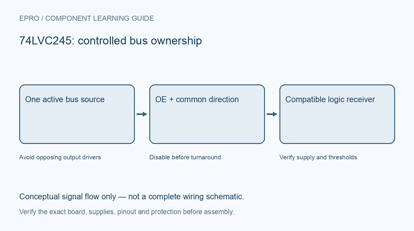
A 74LVC245 Arduino experiment should prove one direction with harmless logic loads before joining two active buses. This workflow refers to TI’s SN74LVC245A and keeps OE, DIR and source ownership explicit so a software mistake does not create output contention.
Check the exact suffix and supply
Confirm the fitted device and package pinout. Use the specified low-voltage supply rather than powering VCC from 5 V because the inputs are tolerant. Check common ground, local decoupling and the voltage limits of every host or receiver pin involved.
Hold OE inactive during initialization
Bias OE high through an appropriate arrangement so the drivers remain disabled while the host starts. Configure direction and source pins before enabling the transceiver. A disabled output is high impedance and may require receiver-side biasing if a defined idle logic level is necessary.
Verify DIR on one channel
With only one intended source active, check that DIR high transfers A to B and DIR low transfers B to A as documented for this part. Use a high-impedance measurement or safe input load. Keep every other potential driver released while confirming the mapping.
Define unused input-side signals
Unused or temporarily undriven input-side lines need valid levels appropriate to the experiment. Do not tie an output to a rail in a way that will cause contention when direction changes. Account for the fact that changing DIR changes which side is being driven.
Sequence turnaround through a disabled interval
Disable OE, release the old source, establish the new direction and new source state, then enable only after the applicable timing requirements are satisfied. Do not treat a quick DIR write as automatic arbitration between two microcontrollers that can both drive the same wire.
Check actual receiver compatibility
Verify low and high states under the intended load, including whether a lower-voltage output meets the destination’s high threshold. Then test at a conservative data rate with the real wiring. Input tolerance alone is not evidence of an adequate output level or a clean timing margin.
Newest in the store


Exercise startup and off states safely
Test controlled host resets and the intended disable state without deliberately creating opposing outputs. Review the exact Ioff and power-sequence conditions before using separately powered boards. A successful low-speed logic test does not establish galvanic isolation or suitability for arbitrary high-energy loads.
Frequently asked questions
Should OE be low before direction and sources are configured?
No. Keep the drivers disabled until source ownership and direction are valid.
Why can a disabled bus read unpredictably?
High-impedance lines can float unless the surrounding circuit defines an idle state.
Availability and illustration note
No matching Epro product was returned by the catalog search on 21 October 2026 UTC. This learning guide does not assert stock, a selling price or compatibility of an unidentified substitute. The illustration is an original conceptual signal-flow diagram, not a product photograph or complete wiring schematic.
Related Epro reading
For a first bench setup, review breadboard connections and continuity checks and I2C voltage-level translation. These guides do not replace the exact module schematic.
Technical references and limitations
Source: Texas Instruments SN74LVC245A datasheet. Electrical limits apply to the named part, not automatically to every carrier board. This is a documentation-based learning workflow, not a claim of independent hardware testing, traceable calibration or safety certification.