


ADS1115 ADC: 7 Checks Before Buying

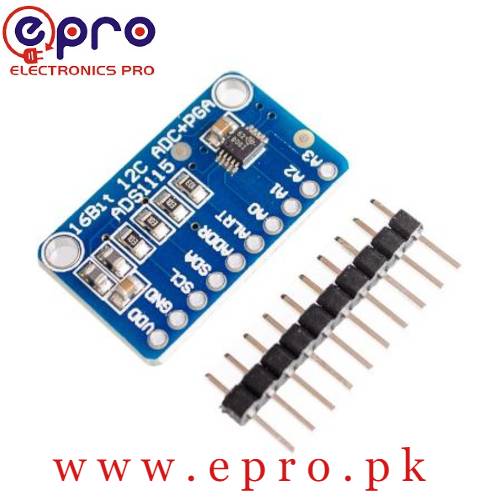
An ADS1115 adds an external analog-to-digital converter to a controller over I2C. It can help with slowly changing sensor voltages, but the words 16 bit do not guarantee that a finished breadboard instrument will achieve laboratory accuracy.
The useful buying questions concern input limits, channel timing, gain and the actual breakout board. This guide explains those choices before the first wire is connected; it does not report an independent performance test of the supplied module.

ADS1115 module price and package
| Listed item | Price (PKR) | Project role |
|---|---|---|
| ADC ADS1115 16bit Analog to Digital Converter in Pakistan | 890 | External ADC module for low-voltage analog measurements |
Price snapshot: Epro listings checked on 18 October 2026. Confirm the current price, availability, delivery charges and package quantity on the linked page before ordering. These are dated listing prices, not a quotation or an independent performance test.
The ADS1115 converter listing describes four analog inputs, a programmable gain amplifier and I2C communication. Check the photographs, supplied headers and board labels against the intended assembly. A lower-priced listing is not a substitute if its item is unavailable or its package differs.
1. Match the converter to a slow signal
The Texas Instruments ADS1115 datasheet specifies selectable conversion rates from 8 to 860 samples per second. The converter is suitable for many slowly varying sensor signals, not an automatic replacement for an audio interface or a high-speed oscilloscope.
Library overhead and I2C transactions also consume time. Decide how quickly the physical signal changes and how many readings the application actually needs. Printing every reading to a slow serial connection can further limit a demonstration’s update speed.
2. Understand the channel multiplexer
Four single-ended inputs do not mean four simultaneous converters. The input multiplexer selects which measurement reaches the converter. Alternatively, appropriate input pairs can be used for differential measurements under the manufacturer’s electrical conditions.
If several channels are read in sequence, their measurements occur at different times. Do not claim 860 samples per second on every channel at once. Applications that require simultaneous sampling need a different acquisition plan and hardware chosen for that requirement.
3. Respect supply and physical input limits
The chip supports a 2.0–5.5 V supply range. The breakout board and the controller’s logic levels still require separate checking. For a first ESP32 project, an appropriately compatible board powered at 3.3 V keeps the I2C pull-ups within the controller’s logic domain.
Newest in the store


For the beginner single-ended circuit, keep each analog input between ground and the converter supply. Do not connect mains, a battery pack above the supply, or a negative voltage directly. A divider, protection network or isolation stage must be designed for the actual source before measurement.
4. Do not confuse gain with input protection
The programmable full-scale settings extend from ±0.256 V to ±6.144 V. Those numbers describe the conversion scale; they do not override the electrical limits on the pins. Selecting a ±6.144 V range does not make a 3.3 V-powered input safe for a 6 V source.
Higher gain can provide smaller numeric steps for a small signal, but it can also cause a reading to clip sooner. Choose a range above the expected signal while respecting the supply rails. Compare the result with a suitable reference before drawing accuracy conclusions.
5. Plan the I2C address
The ADDR connection selects one of four addresses, 0x48 through 0x4B. The common ground-selected address is 0x48. Check the actual board connection rather than assuming every module has the same address or that a product-page shorthand is a complete address table.
Multiple modules need different supported addresses and compatible bus pull-ups. An I2C scan can confirm acknowledgment, but it cannot establish that the analog wiring is safe or that the measured voltage is correct.
6. Budget for the whole measurement chain
Sensor noise, grounding, source impedance and wiring all affect useful results. A 16-bit output word does not remove power-supply noise or calibrate a voltage divider. Keep the first test short and electrically simple, then compare stable readings against a suitable meter.
Label the result in the units actually measured. An ADC returns a representation of voltage, not automatically pressure, current or force. Each sensor conversion needs its own documented transfer relationship and a sensible validation procedure.
7. Start with one channel
Use the ADS1115 ESP32 wiring and code guide to read one low-voltage potentiometer before adding more sensors. Confirm the supply, address and scale first. Only then expand channel count, averaging or logging; none of those software additions can repair an unsafe input connection.