


CD4017 Decade Counter: 7 Clock and Output Checks

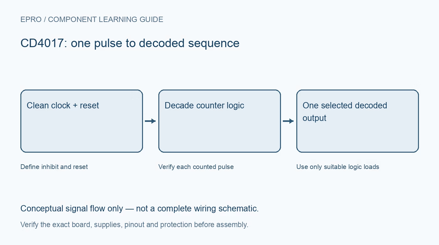
A CD4017B advances through ten decoded output states. It is useful for understanding sequences and divide-by-ten behaviour, but it is not a binary-number output register or a power driver. This guide uses the TI CD4017B documentation and separates the bare component from complete flashing-light kits.
Understand the decoded sequence
The device normally selects one of ten decoded outputs in sequence. A high reset returns the counter to its zero-count state, selecting the corresponding decoded output rather than clearing every output low. Verify this behaviour before interpreting a lit zero-position indicator as a reset failure.
Choose a compatible supply and logic interface
The referenced recommended supply range is 3 to 18 V, but control thresholds and output levels still depend on that supply. A high-voltage-capable counter is not automatically compatible with a lower-voltage microcontroller. Begin with a shared low-voltage design whose logic levels meet the documented requirements.
Plan clock and inhibit together
The ordinary counting arrangement advances on the positive clock transition while clock inhibit is low. Inhibit high prevents that normal clock advancement. Keep control signals stable according to the timing requirements rather than using an uncontrolled enable change as a substitute for a clean counted pulse.
Treat contact bounce as multiple clocks
The clock input has Schmitt-trigger action, but a bouncing switch can still produce several real transitions. Use a suitable debounced source when one press must equal one count. A visually rapid jump through several LEDs may be an input-conditioning problem rather than a faulty counter.
Check output drive under load
Decoded outputs have limited current capability and voltage drop under load. Choose indication resistors and external drivers from the electrical tables rather than assuming ten channels can power arbitrary loads. Do not attach relay coils, motors or high-power lamps directly to the counter outputs.
Distinguish carry from an extra decoded channel
Carry output supports the documented division and cascading functions; it is not simply an eleventh one-hot position. A cascaded design must follow the actual clocking and reset requirements. Inspect the timing diagram before using a casual wire connection to create a larger sequence.
Newest in the store


Review kit identity before ordering
A catalog result containing CD4017 may be a complete NE555 flashing-light kit rather than a bare counter or general-purpose carrier. Verify included parts, assembly requirements and schematic separately. A component learning guide does not establish the compatibility, stock or safety of an unidentified kit substitution.
Frequently asked questions
Should reset make all ten decoded outputs low?
No. It returns to the zero-count state with its corresponding decoded output selected.
Will a Schmitt clock input always count a push-button once?
No. Contact bounce can still generate multiple valid clock transitions.
Availability and illustration note
The catalog search on 21 October 2026 UTC returned NE555 + CD4017 Red Blue Double Color Flashing Lights Board Kit DIY Kits Electronic UN Assemble Kit. Verify the exact fitted part, carrier schematic, included accessories, current price and availability before ordering; this guide does not establish compatibility from a product title alone. The illustration is an original conceptual signal-flow diagram, not a product photograph or complete wiring schematic.
Related Epro reading
For a first bench setup, review breadboard connections and continuity checks and I2C voltage-level translation. These guides do not replace the exact module schematic.
Technical references and limitations
Source: Texas Instruments CD4017B/CD4022B datasheet. Electrical limits apply to the named part, not automatically to every carrier board. This is a documentation-based learning workflow, not a claim of independent hardware testing, traceable calibration or safety certification.