


PCA9546A I2C Switch: 7 Branch and Pull-Up Checks

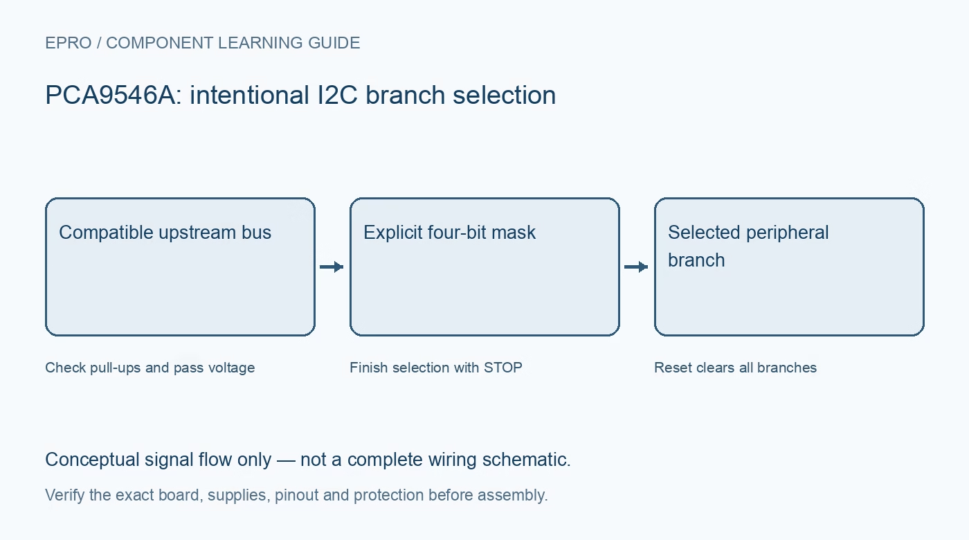
A PCA9546A connects an upstream I2C bus to four selectable downstream branches. It can separate identical-address devices when branches are selected correctly, but it does not rewrite their addresses. Plan topology, voltage levels and recovery before adding a carrier to a low-voltage sensor project.
Identify four branches and the upstream bus
The device routes both clock and data, with one upstream pair and four downstream pairs. Verify connector labeling and the exact manufacturer variant. Do not use an eight-channel device’s pin diagram or assume a channel number printed beside a connector matches a different breakout layout.
Understand the channel bitmask
The four low control bits enable branches independently, so more than one branch can be active. A binary number representing a channel index is not the same as a one-hot branch mask. All branches start deselected after power-on reset, and software must choose the intended connection explicitly.
Isolate duplicate addresses deliberately
Identical-address peripherals on different branches are manageable only while conflicting branches are not connected together. Enabling both can combine responses and make an apparently successful transaction ambiguous. Keep a topology map and choose one appropriate branch before each transaction requiring unique peripheral selection.
Design pull-ups on each bus segment
Upstream and downstream segments require suitable pull-ups to their intended rails. When several branches are connected, pull-up currents and capacitances combine. Account for rise time and sink current rather than adding arbitrary resistors to every header or assuming the switch regenerates an ideal bus waveform.
Check pass voltage for translation
The supply controls the pass-gate high-voltage behavior. Different bus pull-up rails are supported only with a compatible pass-voltage design and input limits. Use the manufacturer guidance for the lowest bus rail; simply powering a carrier at a convenient voltage does not prove every attached device is protected.
Provide a useful reset path
Active-low RESET deselects branches and resets the bus state machine, which can isolate a downstream line held low. Review the documented RESET voltage restriction relative to VCC and its pull-up arrangement. A software I2C reset command cannot be relied on when the bus itself is blocked.
Newest in the store


Specify practical speed and recovery tests
The referenced device supports up to 400 kHz under its timing conditions. Attached devices, wiring and capacitance may require less. Test each branch independently, read the control mask and verify re-selection after reset. This is a functional routing check, not galvanic isolation or a guarantee of hot-plug safety for arbitrary peripherals.
Frequently asked questions
Does the switch change a sensor address?
No. It controls which physical branch is connected to the upstream bus.
Can multiple branches be enabled?
Yes, but address conflicts, combined pull-ups and total capacitance must remain acceptable.
Availability and illustration note
No matching Epro product was returned by the catalog search on 21 October 2026 UTC. This learning guide does not assert stock, a selling price or compatibility of an unidentified substitute. The illustration is an original conceptual signal-flow diagram, not a product photograph or complete wiring schematic.
Related Epro reading
For a first bench setup, review breadboard connections and continuity checks and I2C voltage-level translation. These guides do not replace the exact module schematic.
Technical references and limitations
Source: Texas Instruments PCA9546A datasheet. Electrical limits apply to the named part, not automatically to every carrier board. This is a documentation-based learning workflow, not a claim of independent hardware testing, traceable calibration or safety certification.