


CD4017 Arduino: 7 Reset and One-Pulse Sequence Checks

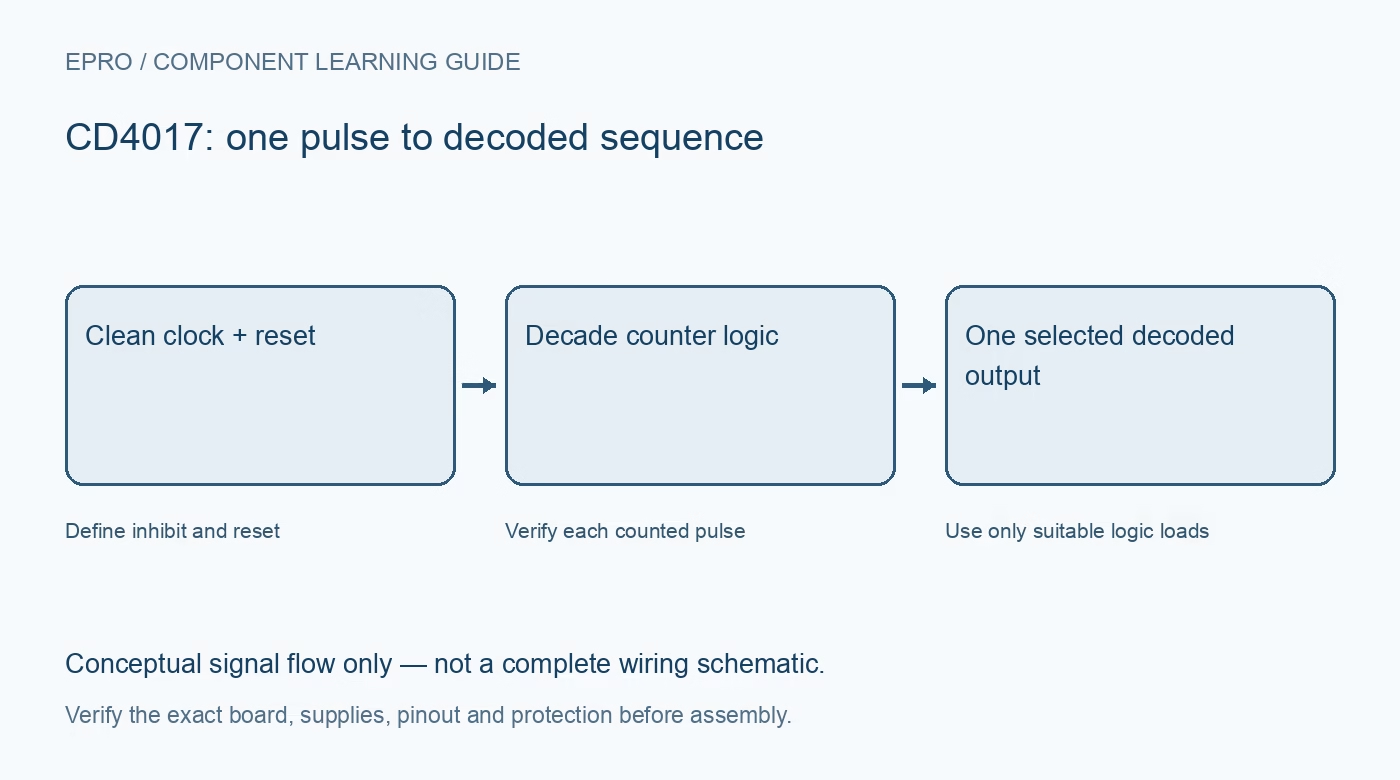
A CD4017 Arduino demonstration should use a deliberately generated slow clock before introducing switches or a separate oscillator. Verify reset and the decoded output sequence with safe logic loads, keeping the host input limits separate from the counter’s supply capability.
Check supply and package orientation
Identify power, ground, clock, reset and inhibit from the exact TI CD4017B pin drawing. Use compatible low-voltage logic rails and local decoupling. Do not power the counter from a higher supply and route its decoded outputs directly into an unprotected lower-voltage host.
Define startup control levels
Keep clock and inhibit at known states while configuring host pins. Ensure reset is also defined rather than floating. Software does not run instantaneously at power-up, so include appropriate hardware biasing where a predictable initial state is needed.
Apply a deliberate reset sequence
Assert reset for the documented interval, then release it with the required timing before normal clocking. Confirm the zero-count decoded output is selected. Reset does not mean every indicator must be dark, and a board with reversed LED polarity can make visual interpretation misleading.
Generate one clean slow pulse
With inhibit low, produce a single positive clock transition and inspect the next decoded state. Keep the pulse widths and control setup intervals within the datasheet requirements. Start slowly enough to observe each position rather than assuming a software delay establishes electrically clean edges.
Verify all ten physical positions
Walk through the sequence and map every decoded output against the package drawing. Indicator wiring is not necessarily in numerical order around the package. Use conservatively resistor-limited LEDs or suitable logic inputs, never a direct high-current load as proof that the counter has advanced.
Test inhibit without an uncontrolled clock
Hold the clock low while changing inhibit for a simple first test, then verify pulses are ignored in the inhibited condition. Restore the defined enable state before resuming the sequence. If a manual button is added later, debounce it instead of relying solely on the clock’s Schmitt-trigger input.
Newest in the store


Keep carry and host resets explicit
Monitor carry only if the test needs it, interpreting it from the documented timing diagram rather than as another decoded position. Check controlled restart and reset behaviour without reconnecting wires under power. These observations establish a limited logic sequence, not safety-rated load control or universal kit compatibility.
Frequently asked questions
Why does the sequence begin with one output active?
The reset state selects decoded count zero, rather than forcing all outputs inactive.
Why can a manual switch skip positions?
A bouncing contact can produce multiple clock edges; start with a clean generated pulse and add proper debounce.
Availability and illustration note
The catalog search on 21 October 2026 UTC returned NE555 + CD4017 Red Blue Double Color Flashing Lights Board Kit DIY Kits Electronic UN Assemble Kit. Verify the exact fitted part, carrier schematic, included accessories, current price and availability before ordering; this guide does not establish compatibility from a product title alone. The illustration is an original conceptual signal-flow diagram, not a product photograph or complete wiring schematic.
Related Epro reading
For a first bench setup, review breadboard connections and continuity checks and I2C voltage-level translation. These guides do not replace the exact module schematic.
Technical references and limitations
Source: Texas Instruments CD4017B/CD4022B datasheet. Electrical limits apply to the named part, not automatically to every carrier board. This is a documentation-based learning workflow, not a claim of independent hardware testing, traceable calibration or safety certification.