


LM339 Arduino: 7 Multi-Threshold and Channel-Mapping Checks

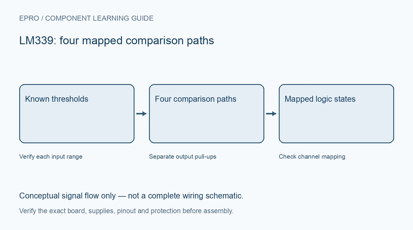
A multi-threshold LM339 Arduino test should first prove each comparator independently. Keep the physical pin mapping and output pull-up rail visible in the wiring record, then combine the states into application decisions only after the underlying comparisons are repeatable.
Check package orientation and channel functions
Use the exact datasheet drawing for supply, ground, each input pair and output. Channel numbering can vary in documentation even when electrical pin functions match. Do not wire four channels by copying a first-channel pattern around the package without checking every assigned pin.
Use a compatible logic-level output path
Inspect existing LEDs and pull-ups if using a module. Provide each monitored output with an appropriate pull-up to a rail safe for the host input. Four comparator outputs do not become safe at 3.3 V merely because the host is powered from 3.3 V.
Choose comfortable input headroom
For the first test, keep signal and references away from the positive rail and within the actual variant’s common-mode limits. Use a known low-voltage source. A divider that spans the entire supply does not guarantee every endpoint is a valid comparator test condition.
Verify one channel before adding references
Drive a signal clearly to each side of its reference and observe actual high and low output voltages. Record polarity and physical pin number. Use this simple test to resolve wiring errors before adding a resistor ladder, interrupt handlers or a display that can obscure the raw state.
Map thresholds and expected combinations
When several channels are enabled, document which output should change first as the signal rises and the expected reverse sequence as it falls. Include offset, reference tolerance and any hysteresis. An unexpected state combination should trigger diagnosis, not be silently renamed as a new valid range.
Keep unused inputs and noise controlled
Give unused channels stable valid input conditions and leave their outputs free. Use supply decoupling and a deliberate analog return path. If a threshold chatters, examine noise and circuit hysteresis before smoothing the host log and declaring the electrical output stable.
Newest in the store


Test startup and logic-only recovery
Check initial host states and a controlled restart without connecting an actuator. Keep a disconnected or invalid test signal distinct from a trustworthy application condition through an intentionally designed fault strategy. This demonstration does not provide calibrated voltage measurement, electrical isolation or safety-rated protective action.
Frequently asked questions
Why can four outputs produce an impossible range pattern?
Check channel mapping, reference order, polarity, noise and operating headroom before changing the interpretation.
Does a stable filtered display prove the raw outputs are stable?
No. Inspect the electrical states and transition behaviour separately from display filtering.
Availability and illustration note
The catalog search on 21 October 2026 UTC returned LM339 Quad Comparator in Pakistan. Verify the exact fitted part, carrier schematic, included accessories, current price and availability before ordering; this guide does not establish compatibility from a product title alone. The illustration is an original conceptual signal-flow diagram, not a product photograph or complete wiring schematic.
Related Epro reading
For a first bench setup, review breadboard connections and continuity checks and I2C voltage-level translation. These guides do not replace the exact module schematic.
Technical references and limitations
Source: Texas Instruments LM339-family quad comparator datasheet. Electrical limits apply to the named part, not automatically to every carrier board. This is a documentation-based learning workflow, not a claim of independent hardware testing, traceable calibration or safety certification.