


TLV9002 Op Amp: 7 Supply and Load-Stability Checks

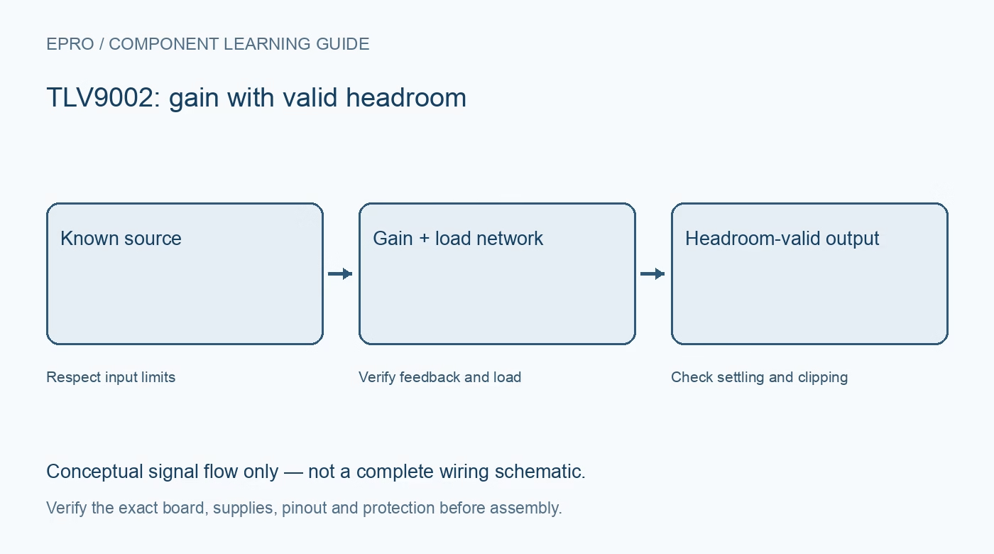
A TLV9002 is a dual low-voltage operational amplifier intended for general signal conditioning. Its rail-to-rail input/output and unity-gain-stable description are useful design features, but the completed circuit still needs a valid feedback network, supply budget and realistic loading assumptions.
Verify the exact variant and package
The TLV900x family includes different channel counts and versions with additional control features. Check the fitted suffix and package drawing rather than assuming every module has the same shutdown pin or channel arrangement. A footprint match alone does not establish electrical interchangeability.
Use the recommended low-voltage supply
The named family operates from 1.8 to 5.5 V. The absolute maximum table is not a normal operating target. Confirm local decoupling, the reference ground and the receiving ADC limits, especially if the amplifier and host are powered from different rails.
Read output swing under the actual load
Rail-to-rail output capability still leaves a load-dependent distance from the rails. A light high-impedance measurement can look better than the eventual loaded circuit. Budget the required signal range against the guaranteed conditions rather than interpreting a typical unloaded observation as a universal output limit.
Consider gain, bandwidth and signal amplitude
The typical unity-gain bandwidth is 1 MHz, but closed-loop gain and noise gain affect useful frequency response. Large-signal slew and settling impose other limits. A slow sensor buffer and a fast waveform amplifier can therefore need very different acceptance tests with the same device.
Evaluate capacitive loading deliberately
TI describes substantial capacitive-load drive capability, but this is not permission for every output cable, capacitor and feedback topology. Use the relevant stability guidance and actual load conditions. Check overshoot and settling instead of assuming an added capacitor always makes the result quieter or more accurate.
Build a complete uncertainty budget
Offset voltage, bias current, resistor ratios, source impedance and reference drift contribute to system error. A typical headline offset is not the maximum error of an assembled sensor channel. Document the operating point and comparison method before applying an unexplained software correction.
Newest in the store


Keep unused channels and claims controlled
Use a stable documented configuration for an unused amplifier and leave its output free from inappropriate loads. Begin with low-risk signal levels and a light measurement input. This learning guide does not establish traceable calibration, medical suitability or an independent safety function for the finished assembly.
Frequently asked questions
Is the absolute maximum supply a recommended test voltage?
No. Stay within the recommended operating range and the conditions of the relevant specifications.
Does unity-gain stable mean every capacitive load is harmless?
No. The actual load and feedback arrangement still need review.
Availability and illustration note
No matching Epro product was returned by the catalog search on 21 October 2026 UTC. This learning guide does not assert stock, a selling price or compatibility of an unidentified substitute. The illustration is an original conceptual signal-flow diagram, not a product photograph or complete wiring schematic.
Related Epro reading
For a first bench setup, review breadboard connections and continuity checks and I2C voltage-level translation. These guides do not replace the exact module schematic.
Technical references and limitations
Source: Texas Instruments TLV900x operational amplifier datasheet. Electrical limits apply to the named part, not automatically to every carrier board. This is a documentation-based learning workflow, not a claim of independent hardware testing, traceable calibration or safety certification.