


AT24C32 Arduino: 7 Page-Splitting and Readback Checks

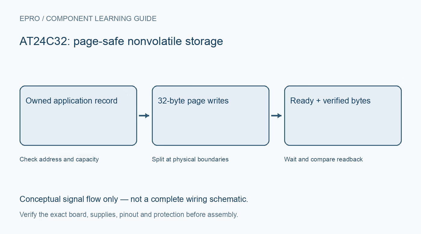
An AT24C32 Arduino test should preserve existing contents and prove that intended bytes survive a completed write. Use the exact suffix documentation and a deliberately reserved test region. A combined RTC carrier needs separate clock and EEPROM handling; a working clock library does not establish memory-write correctness.
Verify identity, voltage and address straps
Read the part marking, carrier schematic and WP connection. Check supply and I2C pull-up compatibility with the host. Determine the memory’s seven-bit device address from its straps independently of any RTC address on the same board, and do not infer identity from an address acknowledgement alone.
Reserve space before any test write
Inspect or back up existing contents and choose a disposable region that the application owns. Check the 4096-byte capacity and reject out-of-range lengths. Do not test a new library by clearing the whole chip or overwriting calibration, configuration or another application’s records without an explicit need.
Send the correct internal address bytes
The device address and internal byte location are different protocol elements. Use the documented two-byte word-address sequence for the cited AT24C32D. A driver intended for a smaller one-byte-addressed EEPROM can repeatedly access the wrong location even while every bus transaction appears to complete.
Split writes at both limits
For the cited device, limit each write to the remaining bytes in its thirty-two-byte physical page. Also account for the host library’s transmit-buffer capacity and addressing overhead. Begin a new write for the next page rather than relying on automatic continuation across a page boundary.
Wait for programming with a timeout
After the stop that begins programming, use acknowledge polling bounded by the documented write-time limit plus appropriate software margin. Report a timeout as an error and stop dependent operations. Do not interpret a temporarily busy device as a valid zero byte or blindly repeat a destructive write indefinitely.
Read back and compare the whole record
Once ready, perform a documented random or sequential read of the intended region and compare every byte. Include a pattern that exposes address-order and boundary mistakes. Check WP if writes appear successful but data does not change; the cited device can acknowledge a protected write without programming it.
Newest in the store


Test persistence and interrupted-record handling
For disposable data, verify a saved record after a controlled power cycle. Use a version, length, checksum and an application-appropriate commit scheme for important records, rather than assuming one I2C transaction is an atomic save. Preserve an explicit invalid-record state and avoid needless rewrites that consume endurance.
Frequently asked questions
Why do bytes near the page start change unexpectedly?
Check for page-write rollover caused by crossing a physical page boundary.
Can I use the RTC battery as proof the EEPROM save completed?
No. EEPROM programming and data validity must be verified independently of the clock backup circuit.
Availability and illustration note
The catalog search on 21 October 2026 UTC returned RTC I2C Module DS1307 AT24C32 Real Time Clock Module in Pakistan. Verify the exact fitted part, carrier schematic, included accessories, current price and availability before ordering; this guide does not establish compatibility from a product title alone. The illustration is an original conceptual signal-flow diagram, not a product photograph or complete wiring schematic.
Related Epro reading
For a first bench setup, review breadboard connections and continuity checks and I2C voltage-level translation. These guides do not replace the exact module schematic.
Technical references and limitations
Source: Microchip AT24C32D/AT24C64D automotive EEPROM datasheet. Electrical limits apply to the named part, not automatically to every carrier board. This is a documentation-based learning workflow, not a claim of independent hardware testing, traceable calibration or safety certification.