


TMAG5273 Magnetic Sensor: 7 Checks for Reliable Angle Experiments

TMAG5273 Magnetic Sensor: 7 Checks for Reliable Angle Experiments
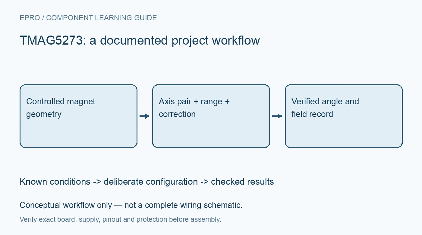
Use TMAG5273 magnetic axes and angle calculations with documented magnet geometry, range checks and calibration rather than assuming any magnet works. This is a documentation-based planning guide, not a report of independent hands-on testing.
1. Separate field measurement from angle
TMAG5273 measures magnetic field components and includes an angle-calculation engine. Texas Instruments describes configurable magnetic channels, averaging and operating modes. The resulting angle depends on the selected axis pair and the magnetic geometry, not simply the presence of a nearby magnet. Define the rotation axis, intended travel and required response first. A magnetic-field reading cannot automatically be interpreted as mechanical displacement without a model and a verified mounting arrangement. Manufacturer documentation.
2. Identify the exact device and carrier
Check the ordering variant, magnetic range, supply requirements, address arrangement and carrier pinout. Inspect I2C pull-ups and controller thresholds before wiring. Similar-looking breakouts may expose different address or interrupt provisions. Confirm identity and read back the configuration after initialization. Keep the magnet and mechanical fixture away from loose ferromagnetic objects while evaluating the setup, and make the arrangement repeatable enough that another session can reproduce its geometry. Manufacturer documentation.
3. Choose the relevant pair of axes
Select the documented channels that correspond to the rotation geometry. Observe the raw field components over a slow controlled turn before accepting the calculated angle. Check that neither selected component clips and that the field magnitude remains suitable throughout the travel. An incorrectly oriented magnet can create a limited or distorted signal while still producing changing numbers. Record axis signs and the mechanical zero rather than correcting them through unexplained display offsets. Manufacturer documentation.
4. Treat gain and offset as measured corrections
Mechanical misalignment and unequal magnetic components can distort the angle relationship. Use the documented correction facilities only after collecting suitable observations across the intended motion. Record how the correction parameters were derived and retain the uncorrected trace. Calibration should not conceal saturation, an unsuitable magnet or a loose mounting fixture. Repeat the evaluation after reassembly because a changed sensor-to-magnet position can invalidate an earlier set of correction values. Manufacturer documentation.
Newest in the store


5. Track freshness and communication integrity
Choose conversion mode, enabled channels and averaging for the required update interval. Read result and status information using the supported transaction format. If CRC is enabled, implement the correct packet coverage and checking rather than assuming a checksum from another sensor will match. Keep a timeout and reject invalid transfers. A repeated angle during a communication failure must be marked stale instead of being interpreted as proof that the mechanism has stopped. Manufacturer documentation.
6. Handle angle boundaries and environmental effects
When calculating movement between readings, account for the wraparound between the end and beginning of a revolution. Test slow turns in both directions and confirm sign conventions. Then evaluate representative mechanical tolerances and nearby magnetic interference under controlled conditions. Do not infer absolute positioning accuracy from a smooth chart or the number of output bits. A metal fastener, a motor or a shifted magnet can change the system response. Manufacturer documentation.
7. Keep a complete TMAG5273 angle record
Log raw axes, computed angle, field context, selected range, correction settings, validity and timestamp. Compare several known mechanical positions with a suitable fixture before using thresholds in an application. The linked AS5600 guide explains why magnet geometry matters, but it is not a substitute for TMAG5273 configuration. This experiment does not establish a safety-rated position sensor; reliable interpretation begins with documented geometry and independently checked mechanical references. Manufacturer documentation.
Related reading: AS5600 Magnetic Encoder: Magnet Geometry and Angle-Sensor Selection.
Catalog note: The exact-part search did not return a matching Epro listing during preparation. Check the current catalog; this guide makes no price, availability or included-accessory claim.