


MAX17048 Fuel Gauge: 7 Checks for Credible Battery Percent

MAX17048 Fuel Gauge: 7 Checks for Credible Battery Percent
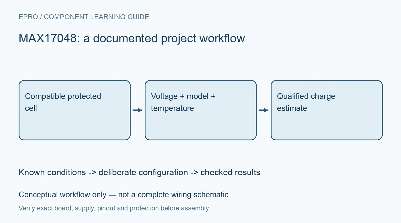
Use MAX17048 battery estimates with the correct one-cell design, register decoding, temperature compensation, alerts and independent battery protection. This is a documentation-based planning guide, not a report of independent hands-on testing.
1. Match the MAX17048 to the cell configuration
The shared documentation covers MAX17048 and MAX17049, but they are intended for different cell configurations. MAX17048 is the one-cell device. Confirm the actual silicon and carrier connections before attaching a battery. Obtain the cell specification and preserve suitable independent protection. A fuel-gauge board is not automatically a charger, a protection circuit or a universal adapter for an arbitrary battery pack simply because its terminals are labeled as battery connections. Manufacturer documentation.
2. Understand what the gauge estimates
ModelGauge estimates relative state of charge without requiring a traditional current-sense resistor. That does not turn the device into a direct current meter or an energy counter. Battery terminal voltage depends on operating conditions and does not uniquely identify remaining charge under every load, temperature or aging state. Define the application’s use of the estimate and avoid displaying a percentage with an implied certainty that the complete battery model and installation have not established. Manufacturer documentation.
3. Verify the electrical and host interface
Review the supply, battery-sense connection, logic levels, pull-ups and alert wiring for the exact board. Keep the initial evaluation within the compatible cell and device limits using an appropriately protected setup. Inspect how other connected equipment, including programmers and chargers, affects grounding and power paths. Communication success is only the first check. It does not prove that the measured voltage corresponds to the intended cell terminals or that protection responsibilities have been satisfied. Manufacturer documentation.
4. Decode voltage and charge with separate rules
The voltage and state-of-charge registers use different numeric representations. Read each field coherently with the documented byte order and apply its own scale and fractional interpretation. Do not use an integer-only conversion that discards meaningful fractional data, or reuse a voltage formula for charge percentage. Preserve raw register values beside decoded results while evaluating firmware. A small collection of known decoding examples can expose byte-order and scaling errors before the host display becomes the main diagnostic tool. Manufacturer documentation.
Newest in the store


5. Implement temperature compensation deliberately
The documented compensation configuration depends on battery temperature and appropriate battery-model parameters. The host must supply the relevant temperature-based adjustment; do not assume that every breakout autonomously handles the complete compensation process. Use a defensible temperature source and vendor-supported parameters for the intended cell characteristics. Document update behavior and initialization settings. Arbitrarily changing compensation until the percentage looks more attractive is not calibration and can conceal a mismatch between the model and the battery. Manufacturer documentation.
6. Use quick-start and alerts for their intended roles
Quick-start reinitializes the estimation process; it is not a button that proves a battery is full or corrects every unexpected percentage. Avoid repeatedly invoking it to force a preferred reading. Configure and handle alerts according to the documented behavior, but keep them distinct from independent overcharge, overdischarge and fault protection. The application should record reset or reinitialization events because those events affect how an apparent change in the reported estimate should be interpreted. Manufacturer documentation.
7. Evaluate estimates without battery abuse
Retain cell identity, load context, temperature handling, configuration and timestamps with observations. Compare behavior only through safe, supervised operation within the cell specifications; do not deliberately overdischarge or create fault currents to demonstrate an endpoint. The linked INA228 guide discusses shunt-based logging, a different measurement architecture. A responsible MAX17048 project communicates estimation limits and retains independent safeguards instead of claiming that a stable percentage display proves battery health, available energy or complete system safety. Manufacturer documentation.
Related reading: INA228 Power Monitor: 7 Steps from Shunt Choice to Energy Logs.
Catalog note: The exact-part search did not return a matching Epro listing during preparation. Check the current catalog; this guide makes no price, availability or included-accessory claim.