


INA237 Power Monitor: 7 Checks for Meaningful Current Data

INA237 Power Monitor: 7 Checks for Meaningful Current Data
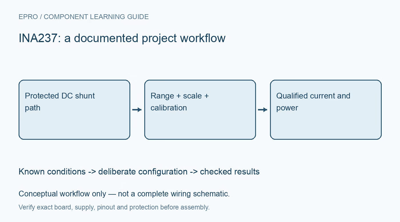
Configure INA237 monitoring with a documented shunt, current scale, calibration register, conversion timing and clear limits on power interpretation. This is a documentation-based planning guide, not a report of independent hands-on testing.
1. Define the INA237 measurement chain
INA237 measures shunt voltage and bus voltage and calculates current and power using configured scaling. Identify the actual current path, shunt and bus connection before reviewing software output. A valid-looking register read does not show that the shunt resistance or current scale matches the hardware. Keep the instrument boundary explicit: a digital monitor is not an isolated mains probe, and introductory evaluation should remain within an appropriately protected low-voltage DC arrangement. Manufacturer documentation.
2. Choose the shunt from the complete load
Select resistance, tolerance, dissipation capability and temperature behavior for the intended current range. Include burden voltage and credible operating transients without deliberately creating fault currents. Use suitable sense routing so shared high-current wiring does not become an unexplained part of the measured shunt. Record the installed component rather than relying on a carrier advertisement. The maximum useful current range depends on the shunt, wiring and thermal conditions, not only the IC specification. Manufacturer documentation.
3. Match the shunt range to the signal
Review the selectable shunt-voltage range and its effect on scaling and clipping. Predict the expected voltage across the installed resistance at relevant load conditions. Check bus-input and common-mode requirements separately from the device supply. Do not apply one family member’s register scale merely because the board labels look familiar. Preserve the chosen range with the data so a later firmware configuration change cannot silently alter the meaning of raw register values. Manufacturer documentation.
4. Program current scaling and calibration deliberately
Derive the current least-significant-bit choice and calibration value with the manufacturer equations for the actual shunt. Keep the calculation, units and configuration revision with the project. The calibration register is part of the device calculation chain, not an optional cosmetic adjustment. Verify initialization and readback where supported before treating current or power registers as meaningful. A measured shunt voltage can appear reasonable even while an incorrect calibration setting makes calculated engineering values wrong. Manufacturer documentation.
Newest in the store


5. Understand conversion cadence and averaging
Select conversion times and averaging according to the required response and noise behavior. Record which measurements are enabled and how the host recognizes a completed update. Bus voltage and shunt conversion are not automatically simultaneous observations of a rapidly changing load. Consider that timing relationship when interpreting calculated power. Host polling speed cannot create a faster independent measurement cadence than the configured conversion process, and repeated reads should not be presented as new samples without checking freshness. Manufacturer documentation.
6. Decode fields according to their roles
Use the documented sign and scale for each register rather than treating every word identically. Shunt measurements can represent bidirectional current, while other quantities use their own representations. The integrated temperature result concerns the die; it is not a direct shunt or battery temperature measurement. Keep alert handling distinct from independent protection. A warning output may support application diagnostics, but it does not replace suitable fusing, current limiting or thermal safeguards in the monitored circuit. Manufacturer documentation.
7. Separate power samples from energy claims
INA237 power observations should not be described as an INA228-style energy accumulation feature without a documented implementation. If the host integrates samples over time, retain timestamps, gaps and validity handling and identify the result as a host calculation. Evaluate the complete chain against suitable reference equipment before claiming accuracy. The related INA228 article is an architectural comparison, not interchangeable registers. This INA237 workflow proposes traceable acquisition and scaling checks without asserting independent load tests or finished-system certification. Manufacturer documentation.
Related reading: INA228 Power Monitor: 7 Steps from Shunt Choice to Energy Logs.
Catalog note: The exact-part search did not return a matching Epro listing during preparation. Check the current catalog; this guide makes no price, availability or included-accessory claim.