


DRV8411A Motor Driver: 7 Checks for Dual-Bridge Control

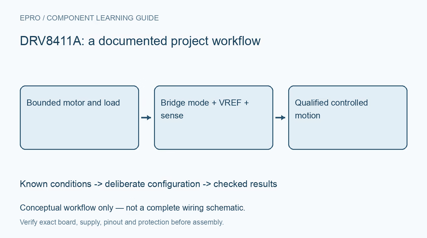
DRV8411A Motor Driver: 7 Checks for Dual-Bridge Control
Plan DRV8411A dual-bridge control with compatible motors, IPROPI sensing, deliberate current regulation, fault handling and thermal limits. This is a documentation-based planning guide, not a report of independent hands-on testing.
1. Define the DRV8411A bridge use
DRV8411A provides two H-bridges for documented brushed-motor and related inductive-load applications. Decide whether the project uses two motors, a stepper arrangement or another supported configuration before assigning pins. Do not assume every pin-compatible family member has identical sensing or regulation behavior. Identify the complete part and carrier revision. The control plan should explain each bridge output and input state, including what happens while the host is booting or resetting. Manufacturer documentation.
2. Size the supply for the real motor
Use the motor specification and application load to assess startup demand, running current and credible stall conditions. The headline peak driver current is not an unconditional continuous rating for any breakout board. Include source capability, wiring, decoupling and bulk capacitance in the design review. Keep early evaluation mechanically restrained and electrically bounded. Do not deliberately lock an unprotected motor to demonstrate a stall, and do not assume a thermal shutdown makes repeated overload operation acceptable. Manufacturer documentation.
3. Review the bridge truth table explicitly
Follow the documented input-state behavior for forward drive, reverse drive and the relevant non-driving states. Keep the host logic compatible with the driver and define a safe default before enabling motion. PWM frequency and input sequencing affect the electrical and mechanical response. A familiar two-input interface does not justify copying another driver’s braking assumptions. Record the intended transitions so an unexpected host reset cannot leave the application relying on an unspecified motor state. Manufacturer documentation.
4. Configure current regulation from VREF and sensing
The device uses the documented VREF and IPROPI arrangement for current regulation. Apply the manufacturer relationships and component requirements to the intended motor limit. Do not assume a potentiometer position or copied resistor value establishes a particular current. Current regulation supports bounded operation but does not replace motor, wiring and thermal analysis. Keep the configured limit distinct from overcurrent fault protection, which serves a different purpose and should not be treated as a routine operating target. Manufacturer documentation.
Newest in the store


5. Interpret IPROPI as a measurement interface
IPROPI supplies a current-related signal that must be converted with an appropriate external arrangement and interpreted according to the driver behavior. Check the host ADC input limits and the conditions under which the signal represents the intended bridge current. PWM and recirculation states affect interpretation. Do not equate an arbitrary instantaneous sample with winding current under every condition. Preserve raw acquisition timing and scale information when evaluating load changes or developing a stall-detection algorithm. Manufacturer documentation.
6. Handle faults and sleep as explicit states
Review undervoltage, overcurrent, thermal and fault-indication behavior using the exact documentation. Define how firmware records a fault and returns to a safe state rather than endlessly retrying motion without diagnosis. Analyze wake and sleep sequencing independently of normal PWM control. A cleared fault indication does not prove that the mechanical obstruction, supply problem or thermal cause has disappeared. Independent safeguards remain necessary where unexpected motion or a hot motor can create a hazard. Manufacturer documentation.
7. Evaluate the complete thermal and motion envelope
Retain motor identity, load, supply, regulation settings, PWM behavior, sense scaling and cooling arrangement with observations. Assess the actual carrier copper and package thermal path rather than quoting only the silicon feature list. The related DRV8871 guide describes another driver configuration, not guaranteed wiring or register equivalence. This DRV8411A workflow proposes controlled evaluation and claims no independent stall tests, continuous-current certification or safe operation for an arbitrary motor merely because it spins. Manufacturer documentation.
Related reading: DRV8871 Motor Driver: 7 Checks for Current-Limited DC Control.
Catalog note: The exact-part search did not return a matching Epro listing during preparation. Check the current catalog; this guide makes no price, availability or included-accessory claim.