


DRV8871 Motor Driver: 7 Checks for Current-Limited DC Control

DRV8871 Motor Driver: 7 Checks for Current-Limited DC Control
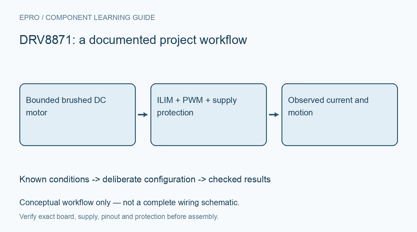
Plan DRV8871 brushed-DC control around stall current, ILIM configuration, coast and brake states, supply transients and realistic thermal limits. This is a documentation-based planning guide, not a report of independent hands-on testing.
1. Begin with the motor, not a peak rating
DRV8871 is an H-bridge driver for a brushed DC motor. Texas Instruments documents current regulation and protective functions, but the maximum or peak current headline is not a guaranteed continuous rating for every carrier. Identify the motor supply rating, expected running current and stall current before selecting hardware. Keep rotating parts restrained and clear of people. A no-load motor demonstration does not establish that the driver can handle the final mechanical load. Manufacturer documentation.
2. Check the carrier current and thermal path
Inspect copper area, connectors, decoupling, protection components and the fitted current-setting resistor. The device operating range does not certify the breakout layout or wiring for all those conditions. Confirm controller logic compatibility and a shared reference where required. Begin with a current-limited suitable supply and no unintended enable signal at startup. Do not connect or disconnect motor wiring while the bridge is actively driving it. Manufacturer documentation.
3. Set ILIM from a defensible target
DRV8871 uses a documented ILIM resistor relationship to establish current regulation. Calculate a target within the motor, device, carrier and supply limits, including component tolerance. Verify the resistor on the actual board rather than trusting a photo from a different revision. Current regulation is not the same as measuring current for telemetry, and it is not a guarantee of safe continuous stall. Avoid destructive stall tests as a casual calibration method. Manufacturer documentation.
4. Distinguish forward, reverse, brake and coast
Use the documented IN1 and IN2 truth table. Both inputs low selects a high-impedance coast state, with the documented sleep behavior; both high selects braking through the low-side path. Driving states establish opposite current directions. Write these states explicitly in software and check safe initialization before attaching the motor. Direction changes and braking can create substantial mechanical and electrical transients, so define a controlled transition policy rather than abruptly toggling at arbitrary load. Manufacturer documentation.
Newest in the store


5. Choose PWM behavior deliberately
Select whether the inactive portion of PWM uses braking or coasting according to the documented operation and application needs. The resulting current decay and mechanical behavior differ. Confirm duty cycle and timing with appropriate measurements; a fifty-percent command does not guarantee half speed under every load. Check wake and sleep effects when very short pulses follow an idle period. Keep firmware scheduling faults from accidentally leaving an unintended drive state active. Manufacturer documentation.
6. Manage energy and heat beyond the chip
A motor and its wiring can return energy to the supply during braking or load changes. Use the manufacturer layout and supply guidance, appropriate local capacitance and a supply arrangement that can tolerate the operating conditions. Monitor temperature under a controlled representative load. Thermal shutdown or overcurrent recovery is a protection event, not a normal speed-control strategy. Repeated fault cycling indicates that the design or operating point needs review. Manufacturer documentation.
7. Keep a DRV8871 operating envelope
Record supply voltage, current-limit configuration, PWM policy, measured load behavior, temperature conditions and any fault symptoms. Start with a small controlled test and increase demands only within an engineered operating envelope. Use independent guarding or shutdown where unexpected motion could harm someone. The linked TB6612FNG and DRV8833 comparison explains driver selection, not interchangeable pin wiring. Reliable DRV8871 control depends on the motor, thermal path and energy handling as well as correct input logic. Manufacturer documentation.
Related reading: TB6612FNG vs DRV8833: 7 Motor Driver Buying Checks.
Catalog note: The exact-part search did not return a matching Epro listing during preparation. Check the current catalog; this guide makes no price, availability or included-accessory claim.