


TPS2121 Power Mux: 7 Checks for Deliberate Source Selection

TPS2121 Power Mux: 7 Checks for Deliberate Source Selection
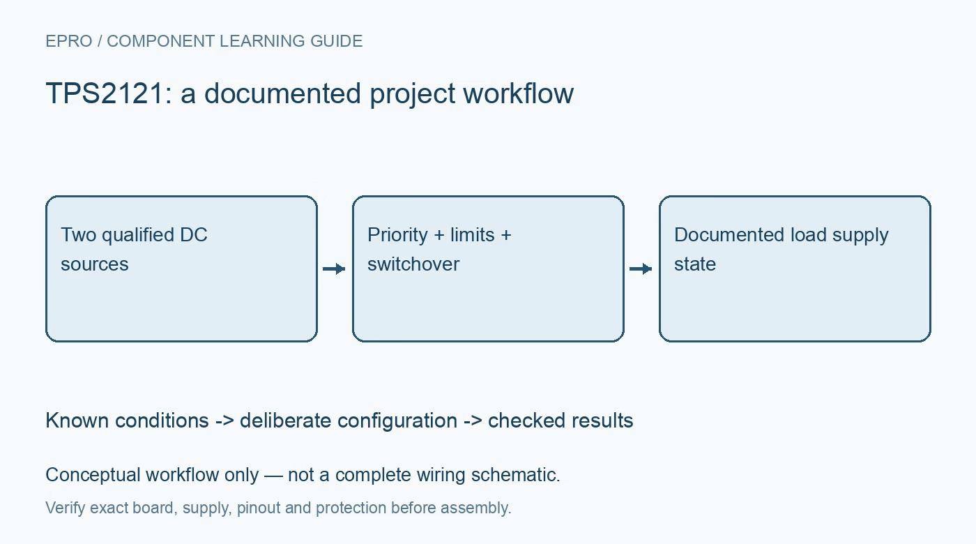
Plan TPS2121 source switching with explicit priority thresholds, source-validity conditions, current limits, output transients and downstream requirements. This is a documentation-based planning guide, not a report of independent hands-on testing.
1. Define the TPS2121 source-selection policy
TPS2121 is a dual-input, single-output power multiplexer. Decide whether the application should prefer a designated source or follow another documented selection arrangement before choosing threshold components. Record the expected source-voltage ranges and the downstream load requirement. A power mux does not inherently regulate both sources to a common output voltage. The load must tolerate the selected source condition, or an appropriately designed conversion stage must provide the required regulated rail. Manufacturer documentation.
2. Verify the exact family member and carrier
The shared TPS212x documentation includes differences between devices. Confirm TPS2121 identity, exposed pins and the actual resistor network on the carrier before applying a schematic or configuration example. Check recommended operating limits for both inputs, output and control pins. Keep evaluation low voltage and appropriately current limited. Do not connect an unknown adapter and battery together merely because the board advertises automatic switching or uses a familiar input connector. Manufacturer documentation.
3. Calculate priority and supervision thresholds
Use the manufacturer equations and tolerances for the selected priority and source-validity arrangement. Include resistor tolerance and source variation when predicting transition boundaries. The intended policy should remain understandable when one source slowly changes or becomes marginal. Do not assume the larger printed input voltage always expresses the desired application priority. Preserve the threshold calculations and pin connections with the hardware revision so observed source changes can be compared with a deliberate specification. Manufacturer documentation.
4. Set current limits for the complete path
Choose the documented current-limit configuration according to source capability, load demand and board thermal limits. Include startup demand and output capacitance in the assessment. A current limit is not a universal substitute for suitable source protection, wiring or connector ratings. Check how a limited or collapsing source affects selection and output behavior. Avoid using repeated protection trips as ordinary operation or assuming that a headline current range applies identically to every carrier and temperature. Manufacturer documentation.
Newest in the store


5. Analyze startup and switchover separately
Review the documented soft-start, input-settling and switchover behavior for the selected configuration. A typical switching-time figure is not a guarantee of zero output disturbance under arbitrary source impedance or load steps. Include output capacitance, effective capacitance under bias and downstream undervoltage requirements. Define acceptable rail behavior explicitly. A processor that appears to stay on during one casual cable swap has not demonstrated that the supply remains valid across the intended operating envelope. Manufacturer documentation.
6. Interpret status without confusing it with regulation
Use the documented status signal to identify the selected path, while distinguishing that indication from an accurate output-voltage or current measurement. Record source states, output behavior and fault conditions together during evaluation. Review reverse-current and supervision functions in the exact circuit rather than assuming that the mux manages battery charging. It does not turn incompatible batteries and adapters into a safe charging system or eliminate the need for independent battery and system safeguards. Manufacturer documentation.
7. Validate the selected rail at the actual load
Plan controlled source transitions using compatible bounded sources and suitable measurement equipment. Retain threshold settings, source impedance, current limit, output capacitance, load profile and instrumentation with observations. The related buck-boost guide explains downstream regulation, a complementary function rather than interchangeable source-selection hardware. This TPS2121 article proposes a documented evaluation boundary and makes no claim of independent switchover measurements, universal uninterrupted operation or safety certification of a complete multi-source power system. Manufacturer documentation.
Related reading: Buck Boost Converter: 7 Checks Before Choosing.
Catalog note: The exact-part search did not return a matching Epro listing during preparation. Check the current catalog; this guide makes no price, availability or included-accessory claim.