


TPS63070 Buck-Boost: 7 Checks Across the Input-Output Boundary

TPS63070 Buck-Boost: 7 Checks Across the Input-Output Boundary
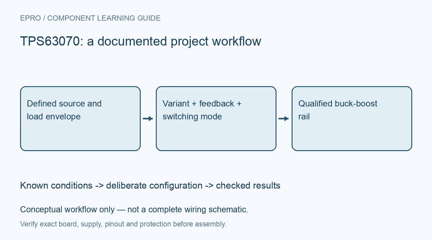
Plan TPS63070 rails with variant-specific settings, realistic output-current budgeting, feedback and VSEL behavior, power-save control and transient checks. This is a documentation-based planning guide, not a report of independent hands-on testing.
1. Identify the TPS63070 family option
The family document covers adjustable and fixed-output options, including differences in output-discharge behavior. Confirm the installed part instead of assuming every TPS6307x board has the same feedback arrangement. Define input range, target rail and expected load states before configuring the converter. Buck-boost operation allows regulation across an input-output crossover, but it does not remove source, thermal or component limitations. Preserve the exact carrier and its existing resistor network with the rail specification. Manufacturer documentation.
2. Distinguish switch current from output current
The headline switch-current value is not a universal continuous output-current rating. Available output depends on input voltage, target voltage, operating mode, thermal conditions and losses. Assess the weakest source condition and the real load profile, including startup and bursts. Boosting requires more input current for a given output power. Do not claim that every board can provide its most favorable example current across the whole input range or under restrictive wiring and source conditions. Manufacturer documentation.
3. Design the feedback and VSEL network
Use the documented feedback relationship for adjustable versions and inspect all components on the carrier. VSEL controls the supported FB2-related resistor arrangement; it is not a generic serial voltage command. Predict both selected voltages and check downstream limits before switching. A host control signal does not prove that the output has settled. Preserve resistor values, tolerances and the intended default selection so reset or disconnected control cannot unexpectedly choose an unsuitable rail. Manufacturer documentation.
4. Choose PS/SYNC behavior deliberately
Review the actual PS/SYNC logic rather than borrowing the polarity of another regulator. The documented arrangement selects forced PWM with a low level and supports power-save behavior with a high level; synchronization has its own clock requirements. The choice affects light-load operation, ripple and energy use. Select it from the application requirement, not a single attractive efficiency figure. Record the mode when comparing observations because different switching policies can produce legitimately different waveforms. Manufacturer documentation.
Newest in the store


5. Treat layout and passives as part of the converter
Select inductor and capacitor values, current capability, effective capacitance and voltage rating using manufacturer guidance. Follow the recommended high-current loop and ground layout. A regulator attached through long jumper leads is not equivalent to the intended compact implementation for ripple or stability evaluation. Keep initial operation protected and low voltage. Device protection features do not replace source safeguards, suitable connectors or the thermal design needed for an actual installed power system. Manufacturer documentation.
6. Check startup and load transitions independently
Review enable thresholds, soft-start, power-good output requirements and the selected shutdown behavior. Evaluate startup at the weakest intended input with the actual output capacitance and representative load. Then assess load steps and input crossover using suitable instrumentation. A steady multimeter reading after startup cannot establish those dynamic behaviors. Avoid repeatedly cycling protection as an ordinary operating policy, and do not assume a power-good indication proves that every downstream task has completed its own reset sequence. Manufacturer documentation.
7. Document the usable operating envelope
Retain variant, source conditions, load timing, feedback components, VSEL state, PS/SYNC policy and thermal arrangement with results. State the conditions of any efficiency or current measurement instead of reporting an unconditional board capability. The linked TPS63900 guide describes another configuration architecture, not matching resistor mappings. This TPS63070 workflow proposes bounded rail checks and claims no independent efficiency curve, universal output-current guarantee or validated transient performance from the converter feature list alone. Manufacturer documentation.
Related reading: TPS63900 Buck-Boost: 7 Checks for Two Voltage Presets.
Catalog note: The exact-part search did not return a matching Epro listing during preparation. Check the current catalog; this guide makes no price, availability or included-accessory claim.