


INA199 Current Monitor: 7 Checks for Gain, REF and Small Shunts

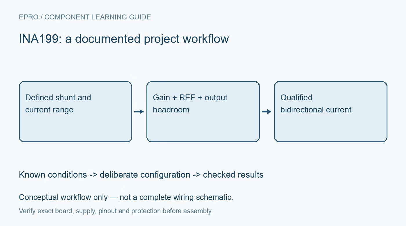
INA199 Current Monitor: 7 Checks for Gain, REF and Small Shunts
Plan an INA199 current monitor with seven checks for gain variants, reference drive, shunt error, input filtering, output headroom and repeatable readings. This is a documentation-based planning guide, not a report of independent hands-on testing.
1. Identify the complete gain and revision code
Start with the full ordering code rather than the family name on a module listing. The x1, x2 and x3 gain options provide 50, 100 and 200 V/V respectively, while A, B and C versions have specification differences. Record the actual package and pin map alongside the gain. A software scale factor cannot correct a physical pin mismatch, and a typical accuracy claim from another revision is not an error budget for this build. Manufacturer documentation.
2. Separate bus voltage from amplifier supply
The INA199 accepts a wide current-sense common-mode range independently of its 2.7 V to 26 V supply. Check the recommended operating conditions and variant-specific absolute limits separately, especially for negative transients near ground. A nominally low-voltage controller does not protect the shunt inputs against a bus spike. Place local supply bypassing near the device and document the common ground and transient-protection arrangement before connecting a powered load. Manufacturer documentation.
3. Calculate shunt loss and low-current uncertainty
Use VSHUNT = I × RSHUNT and shunt dissipation I²R to select a resistor with suitable power, tolerance and temperature coefficient. Very small drops reduce dissipation but make offset a larger fraction of the signal. For perspective, 150 microvolts compared with a 10 millivolt signal is 1.5 percent before other errors; this is an illustrative ratio, not a guaranteed total accuracy. Include copper resistance and Kelvin sensing in the calculation. Manufacturer documentation.
4. Treat REF as an analog signal
The output follows the amplified differential shunt voltage relative to REF. Ground reference is useful for unidirectional operation; an appropriately driven intermediate reference permits positive and negative current observations. Do not leave REF floating or assume a high-impedance divider is equivalent to a stiff reference source. Account for reference noise and source impedance, then verify the zero-current output against the actual reference voltage rather than an assumed half-supply number. Manufacturer documentation.
Newest in the store


5. Keep the amplified output inside its useful range
Calculate the expected output at both current extremes using the selected gain and reference. Reserve margin for the specified output swing under the actual load, offset and reference error. The ADC input range may be narrower than the amplifier supply, so check that boundary separately. A clipped output can look like a stable current reading; flag values near the accepted limits and avoid extrapolating an apparently straight calibration line beyond them. Manufacturer documentation.
6. Evaluate filters without hiding gain error
Input filtering interacts with internal resistor tolerances, so arbitrary series resistors can change the gain error. Follow the manufacturer analysis instead of copying an RC network from an unrelated current monitor. Output filtering also changes the effective drive and settling seen by an ADC. Define the desired bandwidth first, then check resistor matching, capacitor behavior and the acquisition interval. Record the final network values with any calibration results so later changes remain traceable. Manufacturer documentation.
7. Log direction, reference and settling together
Begin validation with a protected source, bounded current and an independent reference instrument. Record zero current, several positive currents and negative currents only when the circuit supports them safely. Store supply voltage, REF, temperature, raw ADC code and elapsed settling time with each point. Distinguish an offset adjustment from a gain correction. Release readings only within the qualified range, and preserve out-of-range or clipping flags rather than replacing them with plausible-looking current values. Manufacturer documentation.
Related reading: INA190 Current Monitor: 7 Checks for Package-Specific Enable.
Catalog note: The exact-part search did not return a matching Epro listing during preparation. Check the current catalog; this guide makes no price, availability or included-accessory claim.