


INA190 Current Monitor: 7 Checks for Package-Specific Enable

INA190 Current Monitor: 7 Checks for Package-Specific Enable
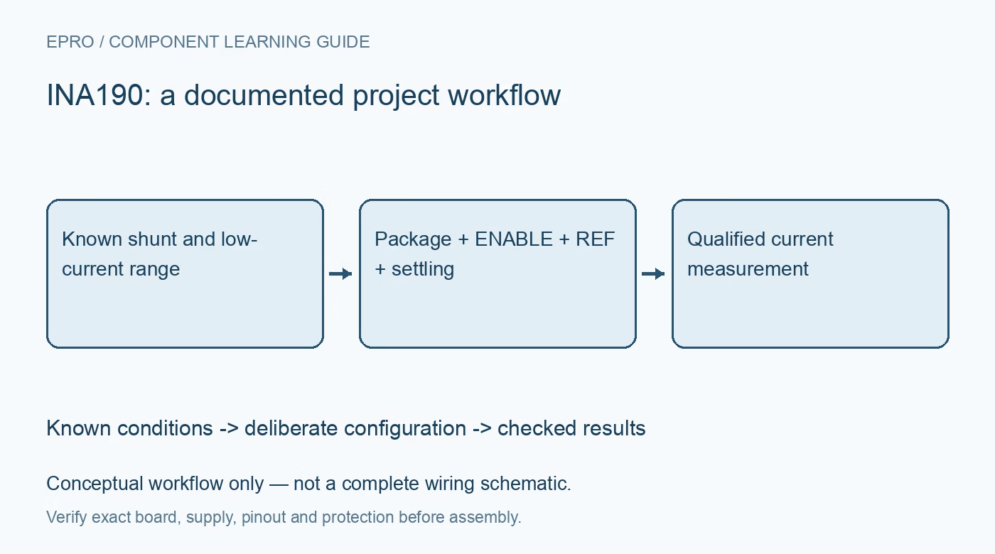
Plan INA190 low-current measurement with the correct package enable capability, REF scaling, shunt leakage budget and settling after wake or overload. This is a documentation-based planning guide, not a report of independent hands-on testing.
1. Check whether the chosen package exposes ENABLE
INA190 is offered in several packages, but ENABLE is not present on all of them. The manufacturer pin table provides it on the eight-pin SOT-23 and ten-pin UQFN versions, not the six-pin SC70 version. Verify the exact order code and symbol before planning power cycling or shared-output sampling. A family feature list mentioning enable does not mean a six-pin footprint contains an undocumented control pin. Package selection can therefore change the measurement architecture, not just the board area. Manufacturer documentation.
2. Match fixed gain and shunt to the required dynamic range
The available gain variants use gains of 25, 50, 100, 200 or 500, rather than the gain list of every related current amplifier. Confirm the fitted variant before converting output voltage to current. A larger shunt improves the low-current signal but increases voltage drop and dissipation at higher currents. Check both ends of the range, including overload and resistor heating. Do not claim microamp capability from the device headline without accounting for the selected shunt and complete board leakage. Manufacturer documentation.
3. Keep bus range, supply and REF as separate constraints
The documented common-mode range extends from -0.2 V to 40 V, while VS operates from 1.7 V to 5.5 V. The monitored bus is not the amplifier supply input. REF establishes the baseline for bidirectional operation, with the output moving above or below it according to current polarity and gain. Verify output headroom against the ADC and load for both current directions. Low supply voltage does not eliminate the need for a suitable reference source and legal pin voltages. Manufacturer documentation.
4. Build a leakage-aware low-current error budget
The low input bias current is valuable for large shunts and small signals, but offset, bias, reference error, resistor tolerance and temperature remain. Board contamination, connector leakage and instrument loading can exceed the current being measured. Use suitable cleanliness, insulation and guarding practices where the application requires them, and verify the measurement fixture as well as the amplifier. Store raw voltages and reference readings during calibration. A zero obtained by software subtraction is not proof that the physical circuit has negligible leakage. Manufacturer documentation.
Newest in the store


5. Treat disabled output as high impedance, not zero
On packages with ENABLE, pulling the pin low shuts down the device and makes its output high impedance. It does not provide a firmly driven zero-current voltage to the ADC. Drive the enable externally or use the documented permanent-enable connection when control is unnecessary. Allow the specified output settling after waking; the datasheet gives a typical interval, not permission to sample immediately after the GPIO edge. Check ADC input bias and sample-capacitor behavior while the source is disconnected. Manufacturer documentation.
6. Review shared-output and overload recovery conditions
The manufacturer illustrates sharing outputs by enabling only one amplifier at a time with the same supply voltage. That is a conditional analog-multiplexing arrangement, not permission to connect multiple active outputs together. Provide deliberate nonoverlap and sufficient settling before each sample. If an input overload saturates the amplifier, the output also needs recovery time after the cause disappears. Distinguish normal enable settling, overload recovery and external filter settling rather than using one arbitrary delay for all three events. Manufacturer documentation.
7. Validate small signals and state changes separately
Begin with a protected low-voltage setup and known currents comfortably above the fixture leakage, then work toward the smallest required range with appropriate instruments. Verify gain, polarity, reference baseline, disable behavior and wake timing on the actual package. Exercise any shared-output sequence without overlapping enabled devices. Save package, gain variant, shunt, source range and acquisition delay. This documentation-based guide makes no independent claim of achieved microamp accuracy, battery life or safe operation at the maximum bus rating on an untested board. Manufacturer documentation.
Related reading: INA181 Current Amplifier: 7 Checks for REF and Shunt Errors.
Catalog note: The exact-part search did not return a matching Epro listing during preparation. Check the current catalog; this guide makes no price, availability or included-accessory claim.