


DRV8801 Motor Driver: 7 Checks for Decay Modes and VPROPI

DRV8801 Motor Driver: 7 Checks for Decay Modes and VPROPI
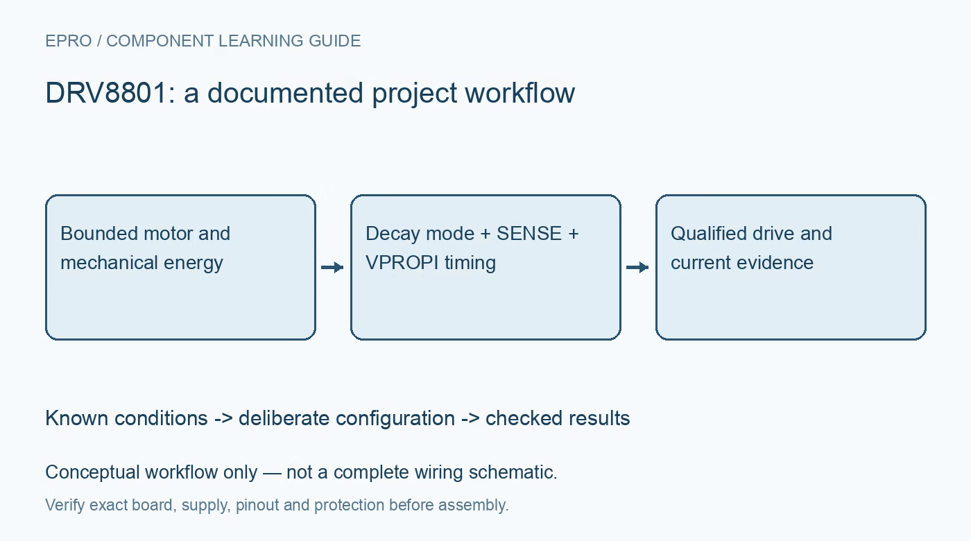
Use DRV8801 motor control with seven checks for decay-mode truth tables, VPROPI sampling, sense-trip behavior, charge-pump startup and bounded motor tests. This is a documentation-based planning guide, not a report of independent hands-on testing.
1. Review the exact full-bridge device and supply
DRV8801 provides one full H-bridge with a PHASE and ENABLE control interface, dedicated sleep and fault pins, and device-specific current-proportional output. The shared datasheet also covers DRV8800, whose corresponding analog function differs. Verify package pins and do not connect VPROPI using a DRV8800 VREG example. Establish a protected supply and motor envelope with margin to all applicable limits, including regenerative transients, before enabling a secured mechanism. The headline peak current is not a universal continuous-load rating. Manufacturer documentation.
2. Do not equate ENABLE low with coast
The MODE1 and MODE2 settings affect how the bridge behaves when ENABLE is low. Depending on the truth-table selection, it can brake through low-side or high-side conduction or use fast-decay synchronous recirculation. None of those should be casually labeled a universal high-impedance coast command. Read the complete control table and define stopping behavior explicitly. Direction reversal also needs a deliberate bounded sequence, especially where stored mechanical energy can raise the supply or produce a hazardous motion. Manufacturer documentation.
3. Provide the specified charge-pump network
The high-side gate drive uses a charge pump and external capacitors. Follow the documented connections between CP1 and CP2 and between VCP and the motor supply, including voltage rating and close placement. These nodes are not spare logic or auxiliary-power pins. After releasing nSLEEP, allow the specified wake behavior before expecting normal drive. Capture startup under a bounded load, because an output command issued too early can be mistaken for a wiring or control-polarity fault. Manufacturer documentation.
4. Calculate the sense-trip path separately from measurement
A resistor from SENSE to ground develops a voltage used for both the proportional output and a sense-based overcurrent threshold. The datasheet describes a nominal 500 millivolt trip relationship, giving an illustrative ITRIP = 0.5 / RSENSE. Review threshold tolerance, resistor pulse power and the protection retry behavior. This is not the same as a programmable smooth fixed-off-time current regulator. Keep the normal sense voltage below the documented boundary and do not use protection cycling as routine motor-current control. Manufacturer documentation.
Newest in the store


5. Understand what VPROPI actually observes
For positive sense voltage, VPROPI is nominally five times the SENSE voltage. It remains at zero for negative sense voltage and falls to zero during slow-decay recirculation. Consequently, a zero reading does not independently prove zero motor-winding current. Grounding SENSE directly also removes useful proportional-current information. Include the actual sense resistor and PWM state when converting voltage to current, and check that the resulting signal remains within the host ADC input range rather than assuming logic-supply compatibility. Manufacturer documentation.
6. Synchronize ADC sampling with bridge state
The manufacturer recommends an RC network when connecting VPROPI to an ADC. Select it with the sampling interval, expected PWM ripple and acquisition requirements in mind. A filtered observation depends on which drive and recirculation intervals contribute to the waveform; an arbitrary sample is not automatically average motor current. Record ENABLE, PHASE and decay configuration with current data. Compare against an appropriate independent measurement under controlled conditions before using VPROPI for a current threshold or load diagnosis. Manufacturer documentation.
7. Validate faults and stopping in a safe fixture
Secure the motor, limit available energy and provide an accessible disconnect. Test the intended drive, stop and sleep states while observing supply voltage, current and nFAULT through a suitable pull-up. Review the documented retry policy before allowing unattended operation; repeated recovery against a persistent fault can continue stressing the load. Keep thermal and mechanical conditions in the acceptance record. A successful unloaded spin or a plausible VPROPI reading alone cannot qualify braking, fault handling or continuous loaded operation. Manufacturer documentation.
Related reading: DRV8848 Dual Motor Driver: 7 Checks for Parallel Mode and Current.
Catalog note: The exact-part search did not return a matching Epro listing during preparation. Check the current catalog; this guide makes no price, availability or included-accessory claim.