


DRV8848 Dual Motor Driver: 7 Checks for Parallel Mode and Current

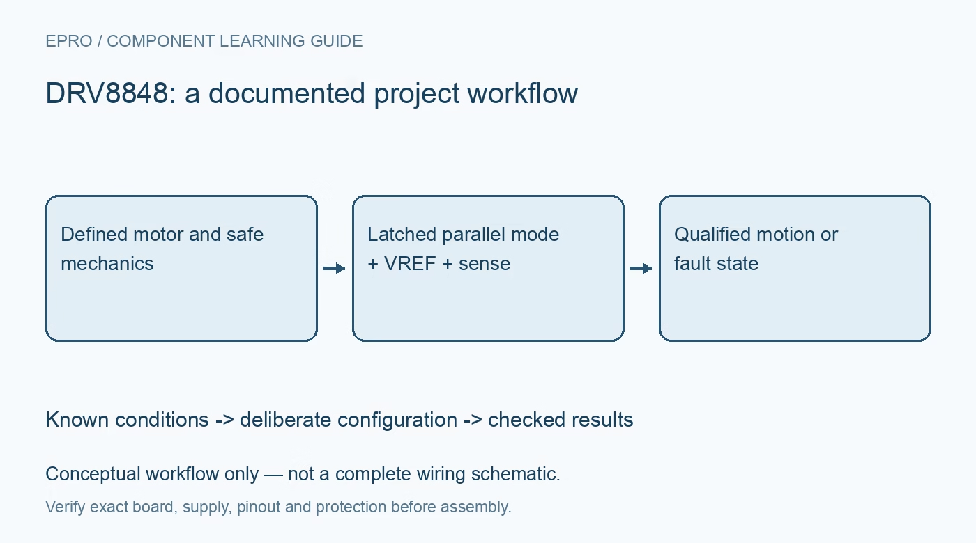
DRV8848 Dual Motor Driver: 7 Checks for Parallel Mode and Current
Configure a DRV8848 dual motor driver with seven checks for startup-latched parallel mode, bridge truth tables, current regulation, faults and thermal limits. This is a documentation-based planning guide, not a report of independent hands-on testing.
1. Bound the supply and mechanical experiment
DRV8848 contains two full H-bridges for a 4 V to 18 V motor supply. Establish motor voltage, winding resistance, startup current and the mechanical load before enabling either bridge. Secure moving parts and provide an accessible power disconnect. Use a current-limited source appropriate to the experiment and review bulk capacitance and regenerative energy. The device protections are not a substitute for a safe test fixture, an upstream fuse where needed or a system-level motion policy. Manufacturer documentation.
2. Treat current headlines as conditional limits
The datasheet describes up to 2 A per bridge or 4 A in parallel under specified operating and thermal conditions. Those figures are not guaranteed continuous current for every PCB. Evaluate conduction loss, switching loss, exposed-pad soldering, copper area and ambient temperature. The actual motor startup and stall currents can greatly exceed normal running current. Select wiring, connectors and sense resistors for the intended bounded case, then verify temperature under representative operation rather than relying on the headline rating. Manufacturer documentation.
3. Use the correct two-input bridge truth table
For each bridge, input 00 gives high-impedance coast, 01 and 10 command opposite directions, and 11 drives both outputs low for brake. Braking and coasting are electrically different states and can produce different stopping and supply behavior. Define a deliberate direction-change sequence instead of reversing under uncontrolled load. Remember that the A input pins are tri-level for mode detection; leaving them floating is not equivalent to commanding zero. Verify all states first without a hazardous mechanism attached. Manufacturer documentation.
4. Select parallel mode at the documented latch event
To enter parallel operation, leave AIN1 and AIN2 high impedance during power-up or while exiting sleep; BIN1 and BIN2 then control the combined driver. Follow the manufacturer output and sense wiring for this mode rather than merely shorting independently driven outputs. Review controller boot pulls and GPIO configuration before releasing nSLEEP. A state applied after the latch event may not select the expected mode, so capture the startup sequence along with the eventual drive commands. Manufacturer documentation.
Newest in the store


5. Calculate current chopping from VREF and sense resistance
The nominal chopping relationship is ICHOP = VREF / (6.6 × RISEN). Use the actual reference tolerance and sense resistance, including temperature and dissipation, to establish a bounded current setting. The fixed-off-time regulator ignores sense voltage during its blanking interval, which also imposes a minimum on-time. Consequently, the formula is not a promise of a perfectly flat instantaneous current. Review low-inductance motors carefully and verify current behavior at startup before increasing mechanical load. Manufacturer documentation.
6. Keep nSLEEP and nFAULT roles separate
nSLEEP is a control input, whereas nFAULT is an open-drain fault indication requiring an appropriate pull-up. Match wake timing and fault-recovery behavior to the relevant protection description. A fault indication does not encode a complete diagnosis, and its absence does not certify acceptable motor temperature or motion. Record the supply and current around a fault, stop the command safely and investigate the cause. Do not implement unlimited automatic retries against a persistent stalled or shorted load. Manufacturer documentation.
7. Validate mode, stopping and regulation together
Test both individual-bridge and intended parallel configurations only with the correct wiring for each. Record power-up pin states, nSLEEP timing, VREF, sense values, motor current and supply excursions. Exercise coast, brake and controlled direction changes with bounded energy and verify fault reporting. Retain thermal observations and load conditions with the acceptance record. A successful no-load spin is useful bring-up evidence, but it does not qualify loaded current regulation, stopping behavior or long-duration temperature performance. Manufacturer documentation.
Related reading: DRV8835 Dual Driver: 7 Checks for Modes and Logic-Supply Sleep.
Catalog note: The exact-part search did not return a matching Epro listing during preparation. Check the current catalog; this guide makes no price, availability or included-accessory claim.