


ADS127L21 Precision ADC: 7 Checks for Programmable FIR and IIR Filters

ADS127L21 Precision ADC: 7 Checks for Programmable FIR and IIR Filters
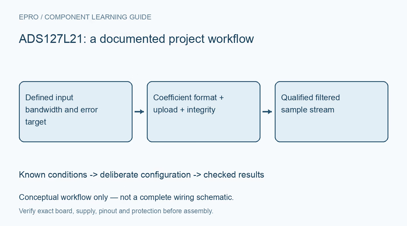
Plan ADS127L21 custom filters with correct coefficient formats, upload ordering, memory CRC, synchronization and measured settling. This is a documentation-based planning guide, not a report of independent hands-on testing.
1. Choose the acquisition mode before filter design
ADS127L21 offers wideband and low-latency paths with different data-rate and response characteristics. The headline rates reach 512kSPS in wideband operation and approximately 1.365MSPS in low-latency operation under specified conditions. Choose the speed range, clock, supply arrangement, oversampling and input range together. Check individual analog-input and reference-pin voltages, including buffer headroom. A custom digital filter cannot repair an overdriven analog input, insufficient reference drive or an invalid supply combination. Manufacturer documentation.
2. Define what the programmable stages must achieve
The programmable FIR and IIR stages belong to the documented filter architecture, not an arbitrary replacement for every stage in the ADC. Specify passband, stopband, gain, noise and latency targets before creating coefficients. Preserve the resulting frequency response and impulse response with the design. An apparently smooth output can hide excessive delay or gain error. Begin from a documented default configuration and establish a known baseline so a custom filter change can be compared against a repeatable acquisition setup. Manufacturer documentation.
3. Encode FIR coefficients in the right format
The programmable FIR3 stage contains 128 taps with coefficients represented as signed 32-bit 1.31 values. Coefficients for a unity-gain passband are typically designed to sum to unity, with unused ending taps padded with zero. Floating-point values cannot simply be sent as their host binary representation. Quantize deliberately and check the sum, symmetry where intended and the actual quantized response. Preserve the complete coefficient list and its revision so a later software rebuild cannot silently change the measurement transfer function. Manufacturer documentation.
4. Follow the coefficient upload order exactly
The FIR bank uses one register address and an internal pointer. The documented upload begins with the most significant byte of h127 and continues down to h0; changing to another register address resets the pointer. Observe the required interframe delay of at least ten clock periods during coefficient access. Handle an SPI error by following the documented recovery procedure rather than continuing an uncertain partial upload. Read back and compare the full bank, then synchronize the ADC after writing coefficients. Manufacturer documentation.
Newest in the store


5. Evaluate quantized IIR stability and artifacts
The IIR option uses four biquads and scaling factors, with signed 32-bit 2.30 coefficients. Its format is not interchangeable with the FIR format. Check the denominator convention, section scaling and quantized pole locations. The manufacturer warns of finite-resolution artifacts when pole radius is above approximately 0.98, even where a floating-point design appears stable. Evaluate zero-input behavior, rounding noise, gain and settling in the actual ADC. A stable mathematical prototype alone does not establish suitability for a precision measurement. Manufacturer documentation.
6. Separate transport CRC from coefficient-memory CRC
SPI CRC checks communication frames, while register and coefficient CRC checks protect different stored contents. The FIR coefficient memory uses a 16-bit CRC over all 128 coefficients, including zero padding; IIR memory uses an eight-bit CRC over its coefficient set. Compute and program the corresponding values using the documented coverage and enable rules. Inspect detailed status flags instead of treating one global error bit as a complete diagnosis. Clearing an indication without correcting the underlying configuration does not restore a valid filter. Manufacturer documentation.
7. Validate the final measurement transfer
Record filter mode, clock, input and reference configuration, coefficient revision, integrity status and data timestamps with every test. Use bounded known signals to check gain, frequency response, clipping and time-domain settling after synchronization. Decode the selected two’s-complement output format correctly, including range and resolution choices. Preserve analog antialiasing and evaluate missed frames at the intended throughput. Report measured behavior separately from simulations and manufacturer examples; a 24-bit output word is not evidence of 24 noise-free bits or a validated custom filter. Manufacturer documentation.
Related reading: ADS127L11 Precision ADC: 7 Checks for Filter Latency, Buffers and CRC.
Catalog note: The exact-part search did not return a matching Epro listing during preparation. Check the current catalog; this guide makes no price, availability or included-accessory claim.