


TMUX136 High-Speed Switch: 7 Checks Beyond the 6 GHz Headline

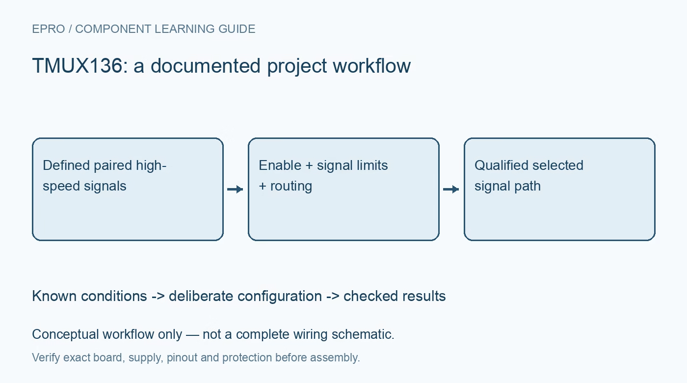
TMUX136 High-Speed Switch: 7 Checks Beyond the 6 GHz Headline
Plan TMUX136 signal routing with active-low enable, paired paths, power-off isolation conditions and realistic board-level bandwidth. This is a documentation-based planning guide, not a report of independent hands-on testing.
1. Define two paired paths with a shared selection
TMUX136 is a two-channel, two-to-one switch that can route a differential pair or two single-ended signals. SEL controls the corresponding path selection together; this is not two unrelated multiplexers with independent address controls. Label both common terminals and both A and B port pairs before routing. Confirm that the required protocol or analog signal can tolerate the switch characteristics. Supporting a high-speed signal does not mean the device regenerates its waveform, translates logic voltage or repairs an impaired link. Manufacturer documentation.
2. Use the documented active-low enable truth table
EN high places both port paths in a high-impedance state. With EN low, SEL low connects the common paths to port A and SEL high selects port B. That enable polarity differs from many general-purpose analog multiplexers. Define reset defaults and verify both selections using safe, recognizable signals. Include the disabled state in software handling so a receiver does not label a floating or stale signal as an active source merely because the address variable still contains a valid selection. Manufacturer documentation.
3. Check analog limits separately from the supply range
The recommended VCC range is 2.3 V to 4.8 V, while the documented analog signal range is zero to 3.6 V. Do not equate an almost five-volt supply with permission to route five-volt analog signals. Check control inputs and the specified supply ramp requirement as separate conditions. Review common-mode level, peak amplitude and transient behavior for both switched paths. Absolute-maximum ratings are stress limits and cannot replace recommended operating conditions when deciding whether a signal interface is supported. Manufacturer documentation.
4. Apply power-off isolation within its test conditions
The device places signal paths in high impedance when VCC is absent and specifies power-off leakage under stated terminal conditions. This feature is useful when another subsystem remains powered, but it is not unlimited surge protection or galvanic isolation. Check the actual powered-off port voltages, possible negative excursions and sequencing against the device limits. Distinguish signal-path isolation from controller-pin behavior. A safe powered-on state does not automatically establish a safe condition while the switch supply is ramping or completely removed. Manufacturer documentation.
Newest in the store


5. Interpret bandwidth together with loss and capacitance
The gigahertz bandwidth figure is a small-signal result under defined loading and measurement conditions, not a guaranteed protocol bit rate on an arbitrary board. On-resistance, on-capacitance, insertion loss and isolation all contribute to the actual channel. For a differential pair, assess balance and the surrounding interconnect as well as a single trace response. Use the relevant frequency-domain characteristics to budget the whole link, including connectors, cable and receiver loading rather than treating the headline bandwidth as a complete signal-integrity qualification. Manufacturer documentation.
6. Route the package as part of the transmission path
The flow-through pin arrangement helps routing but does not eliminate discontinuities from pads, vias and stubs. Keep paired lengths and reference structures appropriate for the chosen interface, minimize unused-branch stubs and place supply bypassing close to the device. Verify package orientation before building a compact footprint. A low-speed continuity test can confirm connectivity while missing a high-frequency routing problem. Include the assembled board and measurement fixture in any simulation or test used to judge the acceptable switching path. Manufacturer documentation.
7. Qualify selection, disable and unpowered operation
Check the selected path with the actual source and receiver, then exercise the other selection, high-impedance mode and loss of switch power. Observe whether control transitions create unacceptable disturbances or stale protocol state. Record signal amplitude, frequency content, loading and supply conditions with the results. No independently measured eye diagram, insertion loss or error rate is claimed here. Preserve the complete channel configuration so later cable or endpoint changes trigger a fresh review rather than relying indefinitely on a nominal bandwidth label. Manufacturer documentation.
Related reading: TMUX1204 Analog Multiplexer: 7 Checks Before Sharing an ADC.
Catalog note: The exact-part search did not return a matching Epro listing during preparation. Check the current catalog; this guide makes no price, availability or included-accessory claim.