


ADXL345 Accelerometer: Range, Interface and Module Selection

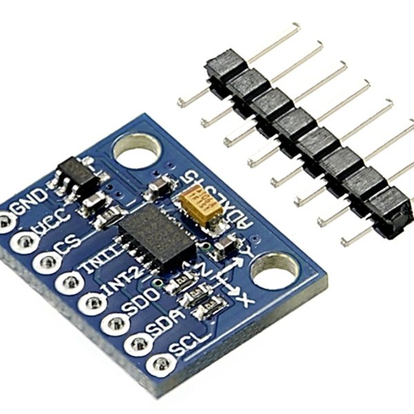
The ADXL345 is a three-axis digital accelerometer for measuring static gravity and dynamic acceleration. It is not a gyroscope or a complete position-tracking system. Select a module by electrical compatibility, measurement range, mounting and data-rate needs before interpreting its numbers as motion.
Choose what you actually need to measure

A stationary accelerometer senses the gravity vector, so a tilted board changes its axis readings even when it is not moving. Dynamic acceleration and vibration add to that response. If the project needs angular rate, compass heading or reliable position, additional sensing and estimation may be required. Do not purchase it on the assumption that three axes means all motion quantities.
Match range and resolution to the task
The device supports ±2 g, ±4 g, ±8 g and ±16 g ranges. A smaller range is useful for gentle tilt experiments, while a larger range can avoid clipping during stronger motion. Full-resolution mode maintains approximately the same scale as range increases; fixed 10-bit mode does not. Record both settings rather than converting every raw count with one assumed constant.
Inspect the breakout power circuit
The IC supply specification is not a blanket approval for five-volt signals. A breakout may contain a regulator without complete logic-level conversion. Verify its schematic and pull-up rail before connecting I2C or SPI to the host. A seller’s originality statement is not independent provenance verification; confirm the actual device and documentation when that matters.
Plan I2C or SPI deliberately
The ADXL345 supports both interfaces. In I2C use, CS must be held in its documented high state and SDO/ALT ADDRESS selects the address. The common seven-bit choices are 0x53 and 0x1D. Do not leave interface-select pins floating or assume a module’s default address matches every online example.
Consider sampling and mechanical attachment
The output-data rate and bandwidth must suit the phenomenon of interest. A low-rate logger can miss faster vibration or misrepresent it through aliasing. A loose sensor hanging on wires also measures movement of the mount. Secure the module to the object being measured and document axis orientation, cable strain and the selected acquisition settings.
Define an honest first acceptance check
Read the device identity, enable measurement mode and inspect axis values while stationary. Rotate the module slowly through known orientations to check plausible gravity response. This is a functional check, not a calibration certificate or a validation of shock-survival marketing. Do not deliberately drop a powered prototype or use an unverified module for safety-critical motion detection.Newest in the store


Relevant Epro listing
Product information and prices were checked on 19 October 2026. This is a current snapshot, not a historical price associated with the publication timestamp. Stock, accessories and checkout prices can change. Listing claims are not independent performance or authenticity certifications.
| Product | Checked price | Stock |
|---|---|---|
| ADXL345-3 Axis Digital Acceleration, Gravity and Tilt Sensor Module in Pakistan | PKR 400 | In stock |
Frequently asked questions
Does ADXL345 measure angular rate?
No. It is an accelerometer, not a gyroscope.
Is full-resolution mode the same as fixed 10-bit mode?
No. The scaling behavior across measurement ranges differs; use the configured mode when converting raw data.
Related Epro reading
Review breadboard connections before assembling a prototype. For controller expansion, the Mega 2560 pin guide explains why pin names and electrical limits must be checked together.
Technical references and test limitations
This guide uses the documentation linked below. The procedures are for a controlled, low-voltage learning setup; no independent hands-on test of the particular seller board is claimed. Record the actual part markings, wiring and firmware version before drawing conclusions from a test.