


DAC8830 Voltage DAC: 7 Checks for Unbuffered Output Accuracy

DAC8830 Voltage DAC: 7 Checks for Unbuffered Output Accuracy
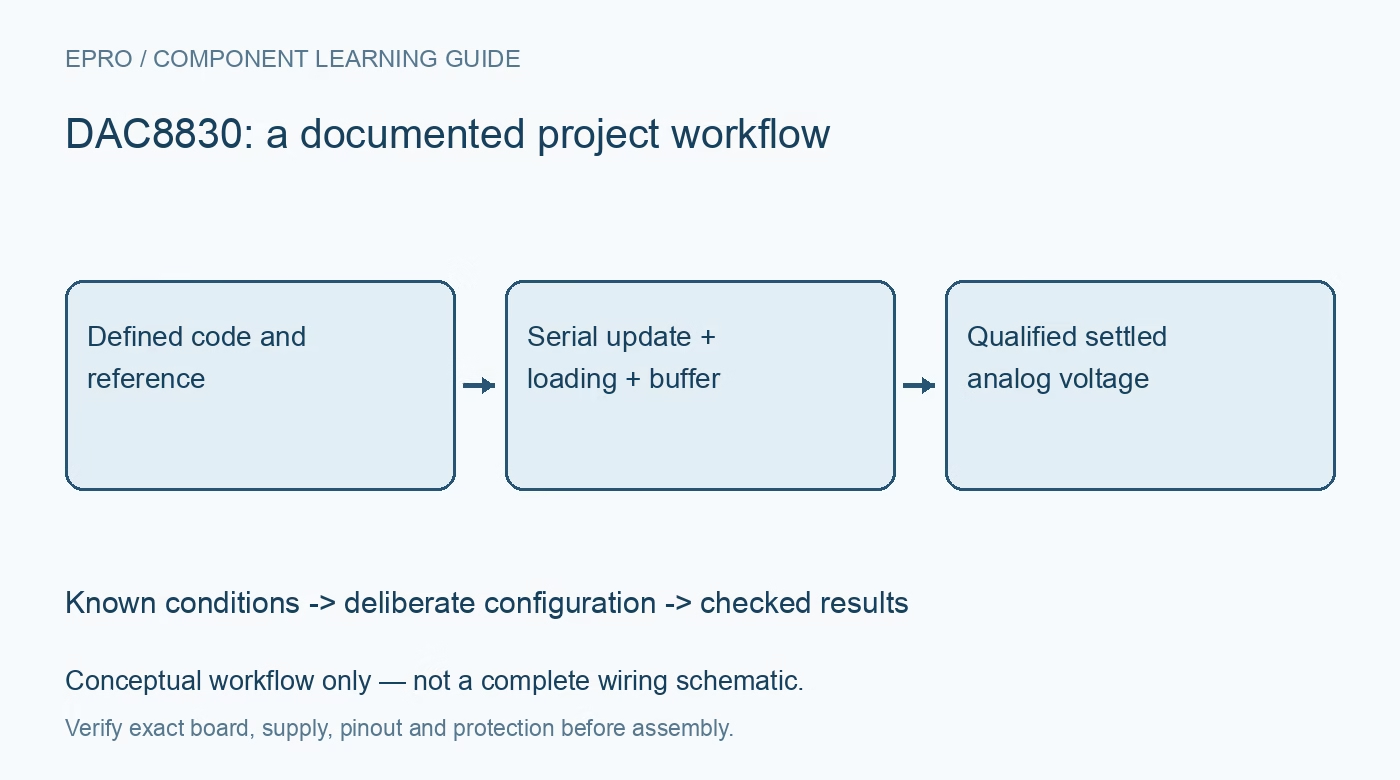
Use a DAC8830 voltage DAC with seven checks for unbuffered loading, external reference drive, sixteen-bit serial updates, startup state and settling. This is a documentation-based planning guide, not a report of independent hands-on testing.
1. Separate DAC8830 from DAC8831 features
Both devices share a sixteen-bit voltage-output architecture, but the DAC8830 is the simpler unipolar part. Do not copy the DAC8831 LDAC, Kelvin-sense or external bipolar-feedback connections onto a DAC8830 pin map. Verify the installed package and actual schematic before choosing a driver. A module may include an external amplifier or reference, so distinguish the converter silicon from the complete board. Record those additional components because they affect both range and accuracy. Manufacturer documentation.
2. Calculate the ideal code range correctly
The ideal unipolar relationship is VOUT = VREF × code / 65536. Code zero requests zero, midpoint requests half the reference, and code 65535 requests one code step below the reference rather than exactly VREF. Keep requested voltages within the allowed reference and supply arrangement and round deliberately when converting to integers. This calculation is a nominal transfer function, not a guarantee of delivered voltage after offset, gain, reference, loading and temperature errors. Manufacturer documentation.
3. Treat VOUT as an unbuffered analog node
The output is not a low-impedance power source. Its approximately 6.25 kilohm output impedance means external loading can create a significant error even when the load seems modest. Evaluate measurement-instrument resistance, leakage and any following resistor network. Where a buffer is needed, choose an amplifier for input bias, offset, common-mode range, output swing and capacitive-load stability. Do not assume a voltmeter observation under one load proves the same voltage will reach a different circuit. Manufacturer documentation.
4. Provide a suitably driven external reference
The reference input presents a code-dependent load, so use the manufacturer reference-drive and bypassing guidance. The specified reference range starts at 1.25 V and extends to the supply; lower reference values reduce accuracy rather than automatically improving useful resolution. Check reference noise, source impedance and dynamic settling during code changes. Route reference and analog ground carefully, separating digital return disturbances. Do not infer an internal reference simply because another DAC family member has one. Manufacturer documentation.
Newest in the store


5. Frame the sixteen-bit SPI transfer explicitly
Drive CS low for the complete sixteen-clock word, sending the most significant bit first. Input data is latched on rising SCLK edges, and the rising CS edge transfers the word. The DAC8830 updates its DAC latch immediately with that transfer; there is no separate LDAC scheduling pin. Match setup, hold and logic-voltage limits to the chosen controller. Check the actual waveform before increasing clock speed, especially when isolators, level translators or long interconnects are present. Manufacturer documentation.
6. Distinguish reset state from a qualified output
Power-on reset initializes the data to zero code. That does not guarantee a perfectly zero system voltage while the supply, external reference and any buffer are still starting. Define a safe downstream state until all relevant rails have settled. Consider the order in which the controller and DAC become powered, including unwanted current through digital inputs. If the application needs a different initial voltage, issue and verify a deliberate first command rather than depending on retained software variables. Manufacturer documentation.
7. Measure settling at the actual observation point
Datasheet settling figures apply to stated load and step conditions. A buffer, cable or ADC sampling network adds its own settling and noise behavior. Validate representative small steps and large transitions, recording code, reference voltage, elapsed time and observation bandwidth. Compare zero, midpoint and near-full-scale values with an appropriate reference instrument, but keep calibration correction separate from a claim of sixteen-bit system accuracy. Release a value only after the chosen acceptance band is reached and maintained. Manufacturer documentation.
Related reading: DAC8551 Voltage DAC: 7 Checks for Feedback and Serial Updates.
Catalog note: The exact-part search did not return a matching Epro listing during preparation. Check the current catalog; this guide makes no price, availability or included-accessory claim.