


Joystick Module KY-023: 7 Checks Before Buying

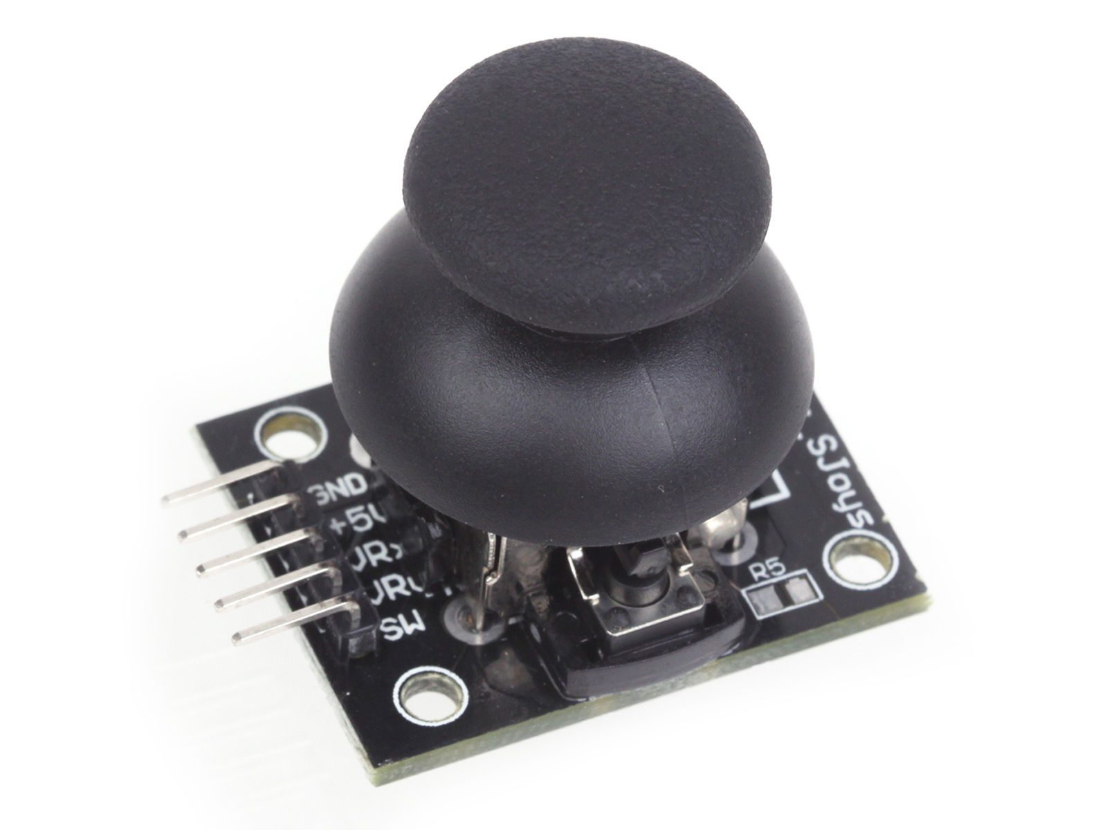
A joystick module provides an intuitive hand-operated input for a low-voltage electronics project. The common KY-023 combines two analog position signals with a push switch, making it useful for exploring menus, direction commands and user-input calibration.
It is not a complete USB game controller or a motor driver. Understanding the signals before buying helps avoid confusing a small analog input board with a digitally communicating gamepad, a Hall-effect joystick or an industrial control device.

Joystick module price and package
| Listed item | Price (PKR) | Project role |
|---|---|---|
| Dual-axis XY Joystick Control Module KY-023 | 140 | KY-023 dual-axis analog joystick module |
Price snapshot: Epro listings checked on 18 October 2026. Confirm the current price, availability, delivery charges and package quantity on the linked page before ordering. These are dated listing prices, not a quotation or an independent performance test.
The KY-023 dual-axis module is listed with five connections: supply, ground, VRx, VRy and SW. Confirm the current photograph, board dimensions and connector arrangement before designing a mounting panel. This guide does not claim a particular service life or independently tested positional accuracy.
1. Understand the two analog axes
A conventional thumb joystick uses two potentiometers moved by a gimbal. Each produces a position-dependent voltage for an analog input. The SparkFun analog joystick explanation illustrates the underlying two-axis mechanism and separate push switch.
The X and Y outputs are not I2C messages and do not provide an angle in degrees automatically. A controller samples the voltages and software interprets them. Moving diagonally changes both axes, while mechanical tolerances can make their usable ranges slightly different.
2. Separate the push switch from a third axis
Pressing the cap operates a switch; it does not measure a third proportional direction. A listing that mentions a button should not be interpreted as a three-axis analog sensor. Read the exact interface before choosing libraries or planning the user experience.
The button needs a defined electrical state, usually through an appropriate pull-up in a beginner Uno arrangement. Mechanical contact bounce also needs consideration when a single press should trigger one action. A raw switch test is not a complete debounced menu implementation.
3. Match analog voltage to the controller
A conventional Uno circuit can use the module’s documented 5 V arrangement. Its axis voltages can approach that supply. Those outputs must not be connected blindly to a 3.3 V-only ADC or GPIO when the joystick is powered at 5 V.
Newest in the store


For another controller, verify the module’s permitted supply, actual output range and the ADC’s input limits. Changing the microcontroller code does not provide voltage translation. Keep the first wiring test unpowered until supply and ground have been checked.
4. Make sure analog inputs are available
Two axis readings need two suitable analog inputs. A conventional Uno has them, but a standard Raspberry Pi GPIO header does not offer general-purpose analog conversion. That platform needs an appropriate external ADC or a different input device.
If an external ADC is used, verify its supply, input rails and sampling requirements. An ADC’s advertised bit count does not establish joystick precision; mechanical centering, electrical noise and calibration can dominate the useful result.
5. Plan calibration and a center deadband
A spring-return stick should not be assumed to rest at exactly half the numeric ADC scale. Record its untouched center and observe the actual endpoints. Do not publish universal minimum and maximum values as though every supplied module had been measured.
A deadband around the observed center can prevent tiny fluctuations from becoming unintended commands. Its size should follow the project’s sensitivity and actual noise. Too large a deadband makes the control unresponsive; too small can cause drift around the resting position.
6. Budget for mounting and the controlled load
A breadboard demonstration and a durable handheld controller have different mechanical needs. Check how the PCB is supported, whether the cap clears the enclosure and whether the connector can be reached after assembly. Avoid transmitting excessive force through unsupported solder joints.
Axis pins provide signals, not motor power. A robot or servo project needs appropriate drivers, power arrangements and software limits. A joystick is not an emergency stop or a certified safety control, and a reading failure should not silently become a maximum-speed command.
7. Prove the raw readings first
Follow the joystick module Arduino wiring and code guide to print X, Y and button states before adding actuators. A clear serial test separates wiring faults from mapping and control logic. Treat gamepad emulation as a separate hardware and firmware decision rather than assuming any Uno becomes a USB HID controller.