


LoRa SX1278 Arduino: Bring-Up and Packet-Loss Checks

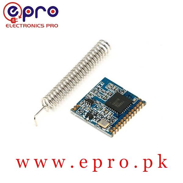
A LoRa SX1278 Arduino test should first prove that the controller can communicate with the radio, then that two compatible radios exchange identifiable packets. Keep electrical checks separate from radio settings and obtain permission for the intended frequency and power before transmitting.
Choose a compatible controller and carrier

Read the actual board’s pinout and supply requirements. The SX1278 itself is a low-voltage SPI radio, so a 5 V Arduino needs documented level adaptation where required; do not assume a carrier regulator also adapts every signal. A compatible 3.3 V controller can simplify the electrical interface but does not remove the need to check pin assignments and power capacity.
Map SPI, reset and interrupts explicitly
Connect clock, MOSI, MISO, chip select and ground according to the controller and module documentation. Route reset and the required DIO/interrupt signals to suitable controller pins for the chosen library. Keep leads short for the initial setup. SPI pins differ among Arduino boards, so an Uno wiring picture is not a universal connection table.
Prove register communication first
Use a maintained library supporting the exact radio and a diagnostic initialization example. Record the library version and configured pins. If initialization fails, inspect supply, reset, chip select, SPI wiring and bus conflicts before changing RF settings. A power LED only proves some part of the board receives power; it does not establish that SPI accesses work.
Match both endpoints before sending packets
Document the permitted frequency and matching modem parameters on both radios: bandwidth, spreading factor, coding rate, header mode, sync configuration and CRC handling as applicable to the library. A compatible antenna and RF band are essential. Use conservative lawful power and appropriate separation, not maximum output with the two antennas touching.
Count packets instead of judging one message
Send a short payload with a monotonically increasing sequence number at a conservative permitted interval. Record received sequence numbers, duplicates, gaps and total counts over a defined test duration. RSSI and SNR are useful observations but do not replace a loss calculation. Log configuration and location so a repeated test is comparable.
Change one condition at a time
After a stable short-range test, change distance, orientation or one modem parameter while keeping a written baseline. Inspect power dips and antenna connections if performance changes unexpectedly. Do not report a guaranteed range from a single successful packet. Keep examples free of confidential data and do not use an unauthenticated hobby radio link as a sole safety-control channel.Newest in the store


Relevant Epro listing
Product information and prices were checked on 19 October 2026. This is a current snapshot, not a historical price associated with the publication timestamp. Stock, accessories and checkout prices can change. Listing claims are not independent performance or authenticity certifications.
| Product | Checked price | Stock |
|---|---|---|
| 433MHZ Wireless RF Receiver Lora Module SX1278 in Pakistan | PKR 1,600 | In stock |
Frequently asked questions
Why does initialization fail before any transmission?
Check power, SPI, chip-select, reset and configured pins first. Radio range settings do not repair a missing wired interface.
Does strong RSSI prove a reliable application link?
No. Measure packet delivery over a defined interval and check errors, duplicates and configuration as well.
Related Epro reading
Review breadboard connections before assembling a prototype. For controller expansion, the Mega 2560 pin guide explains why pin names and electrical limits must be checked together.
Technical references and test limitations
This guide uses the documentation linked below. The procedures are for a controlled, low-voltage learning setup; no independent hands-on test of the particular seller board is claimed. Record the actual part markings, wiring and firmware version before drawing conclusions from a test.