


MAX232 Circuit Diagram: Charge Pump and UART Loopback Checks

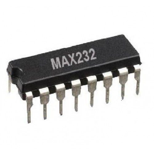
A MAX232 circuit diagram combines a charge pump with two driver and receiver channels. This guide follows the documented TI five-volt device and explains a controlled single-channel loopback. It is not a universal schematic for MAX3232 modules or every pin-compatible derivative.
Use the exact package drawing

For the linked sixteen-pin TI part, VCC is pin 16 and GND pin 15. Channel-one logic input T1IN is pin 11, RS232 output T1OUT pin 14, RS232 input R1IN pin 13 and logic output R1OUT pin 12. Verify the supplied package, notch and manufacturer drawing before applying power.
Build the documented charge pump
Use the datasheet application for C1 between C1+ and C1−, C2 between C2+ and C2−, and the two storage capacitors on the generated positive and negative rails. The referenced MAX232 uses 1 microfarad values. Follow its polarity and bypass details exactly; a text summary is not a substitute for the complete application drawing.
Keep generated rails in their intended role
The charge-pump nodes are part of the line-driver circuit, not spare supply rails for powering another project. Do not short them to logic ground or connect them to host GPIO. Keep capacitor connections short, inspect solder joints and use suitable component voltage ratings. Capacitor mistakes can prevent the serial side from reaching valid signaling levels.
Map one channel by function
Connect a compatible host UART TX to T1IN and R1OUT to host RX, plus the required logic ground reference. T1OUT and R1IN belong to the RS232 side. Do not swap a true RS232 signal into the logic input because it is called TX on another connector. Leave unused pins as directed by the datasheet and the overall circuit design.
Perform a harmless local loopback
With external equipment disconnected, a documented test can link T1OUT to R1IN on the RS232 side and send a known byte sequence from the host. Returned bytes exercise that driver/receiver path and host routing. Keep the host logic compatible, use matching framing and record exact received data rather than only a terminal’s local echo.
Know what a loopback does not prove
A local return path does not validate the external cable, connector roles, remote handshake requirements or application protocol. It also does not establish isolation or maximum cable length. Disable terminal local echo when judging returned bytes so typed text is not mistaken for a functioning hardware loopback.
Newest in the store


Troubleshoot supply and capacitor faults before speed
No returned data calls for checking the host UART independently, supply, charge-pump assembly and signal directions. Garbled bytes call for framing and baud checks as well as electrical inspection. Do not increase supply beyond the recommended range to force a response. Disconnect the test circuit before attaching a separately verified remote endpoint.
Relevant Epro listing
Product information and prices were checked on 19 October 2026. This is a current snapshot, not a historical price associated with the publication timestamp. Stock, accessories and checkout prices can change. Listing claims are not independent performance or authenticity certifications.
| Product | Checked price | Stock |
|---|---|---|
| MAX232 dual EIA 232 drivers and receiver line bus driver IC | PKR 80 | In stock |
Frequently asked questions
Can the generated negative rail power another circuit?
Do not treat it as a general auxiliary supply. It is part of the documented charge-pump/line-driver operation.
Why can local echo give a false success?
A terminal may display typed text without receiving anything from hardware. Distinguish local echo from returned bytes.
Related Epro reading
Review breadboard connections before assembling a prototype. For controller expansion, the Mega 2560 pin guide explains why pin names and electrical limits must be checked together.
Technical references and test limitations
This guide uses the documentation linked below. The procedures are for a controlled, low-voltage learning setup; no independent hands-on test of the particular seller board is claimed. Record the actual part markings, wiring and firmware version before drawing conclusions from a test.