


OPA2192 Precision Op Amp: 7 Checks for Rail-to-Rail Accuracy

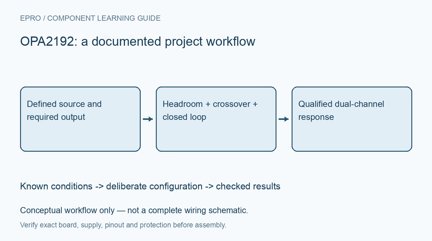
OPA2192 Precision Op Amp: 7 Checks for Rail-to-Rail Accuracy
Plan an OPA2192 analog stage with the correct supply range, common-mode transition checks, output headroom, capacitive loading and dual-channel layout. This is a documentation-based planning guide, not a report of independent hands-on testing.
1. Start from the dual device and its real supply range
OPA2192 is the dual member of the OPAx192 precision amplifier family. Its recommended supply span is 4.5 V to 36 V, or corresponding dual rails, not the lower-voltage range of every similarly named rail-to-rail amplifier. Verify package orientation and both channel pin assignments before assembly. Define the input range, output range, gain and load together. A precision label does not establish that a 3.3 V-only board can operate this part within its specified conditions. Manufacturer documentation.
2. Examine the input-pair transition region
The rail-to-rail input architecture uses complementary input pairs, with a transition region near the positive supply. The datasheet describes possible changes in offset, drift, noise, rejection and distortion within that region. Plot the expected common-mode excursion against the actual supply rather than treating input accuracy as uniform everywhere. For demanding measurements, compare operating points inside and outside the transition region. A single offset measurement at midrange cannot characterize a signal that sweeps across the whole supply span. Manufacturer documentation.
3. Budget output swing with the connected load
Rail-to-rail output means operation close to the rails under documented conditions, not an ideal voltage source that reaches either rail at any current. Check the load-dependent swing limits and the required source or sink current. Include the ADC, resistor network and any cable in that load. Calculate dissipation for both amplifiers when outputs drive substantial current. Thermal protection may prevent damage, but a protected amplifier that stops driving is not delivering an accurate measurement. Manufacturer documentation.
4. Build a complete error budget instead of quoting typical offset
The low headline offset and bias current are typical specifications under particular conditions. Select appropriate maximum limits over the intended temperature and common-mode range, then add resistor tolerance, reference error, thermoelectric effects and source impedance. Bias-current error grows with impedance and imbalance. Keep precision nodes clean and protect them from leakage through contamination or unsuitable components. Calibration can address measured repeatable errors, but it does not automatically remove drift, clipping or changing errors at a different operating point. Manufacturer documentation.
Newest in the store


5. Check bandwidth, slew and settling independently
The 10 MHz gain-bandwidth headline does not guarantee full-amplitude response at 10 MHz or the same bandwidth at every closed-loop gain. Review the required signal bandwidth, slew rate and settling error at the sampling instant. A fast output edge can still take longer to settle within a precision error band. If a multiplexer changes the input, include overload recovery as well. Phase-reversal protection avoids one failure behavior; it does not make overdriven inputs a valid linear operating condition. Manufacturer documentation.
6. Evaluate capacitive load and the unused channel deliberately
The family supports substantial capacitive loads, but stability still depends on gain, layout, feedback and the actual load. Consult the documented capacitive-load guidance before adding a cable or ADC input network. Use any isolation network only after checking its effect on settling. Give an unused amplifier a defined, stable closed-loop connection at a legal input voltage rather than leaving its inputs floating. Decouple the shared supplies locally so activity on one channel does not unnecessarily disturb the other. Manufacturer documentation.
7. Validate the operating envelope with controlled analog tests
Apply safe known inputs at several common-mode levels, then compare measured gain, offset, settling and clipping with the proposed budget. Repeat with the intended load and supply extremes without exceeding ratings. Check both channels and monitor unexpected heating or oscillation with appropriate instruments. Record resistor values, source impedance, temperature and measurement bandwidth. This is a manufacturer-documentation planning guide, not an independent bench report; the final accuracy and stability claims belong to the tested board and configuration. Manufacturer documentation.
Related reading: TLV9062 Op Amp: 7 Checks for Bandwidth, Loading and Variant Pins.
Catalog note: The exact-part search did not return a matching Epro listing during preparation. Check the current catalog; this guide makes no price, availability or included-accessory claim.