


PCA9685 PWM Controller: 7 Servo-Board Buying Checks

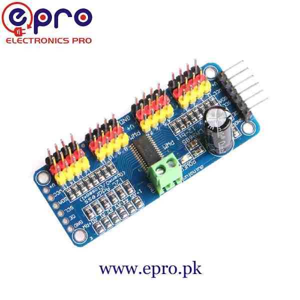
A PCA9685 provides sixteen PWM outputs controlled through I²C. It is often sold as a servo-driver board, but the chip generates control signals; it does not replace the power supply for sixteen motors or provide sixteen H-bridge outputs.
Before buying, distinguish logic power, the board’s separate load-power distribution and the signal timing your application needs. That distinction prevents a common mistake: expecting a small controller’s USB connection to power an entire moving robot.

PCA9685 price and breakout format
| Listed item | Price (PKR) | Project role |
|---|---|---|
| PCA9685 16 Channel Servo Motor Driver in Pakistan | 1,200 | Sixteen-channel PWM/servo breakout module |
Price snapshot: Epro listings checked on 19 October 2026. Confirm the current price, availability, delivery charges and package quantity on the linked page before ordering. These are dated listing prices, not a quotation or an independent performance test.
The Epro PCA9685 listing describes an I²C breakout with address jumpers and three-pin output headers. Verify actual labels, connector polarity and board construction. Do not assume every protection feature mentioned in a general listing is present on every visually similar board.
1. Understand what sixteen channels means
Each channel can have an independently selected duty cycle and phase setting, but the chip uses a common PWM frequency for the channels. It is not sixteen unrelated timers that can each run at any independently selected frequency.
That matters if combining servos and LEDs. A frequency selected for an LED experiment may be inappropriate for a servo. Plan compatible loads on a board rather than relying on a separate channel number to provide independent timing hardware.
2. Separate twelve-bit steps from frequency accuracy
The PWM period has 4,096 timing steps. This describes the counter resolution, not a promise of twelve-bit motor position accuracy or a frequency generator with a perfectly calibrated oscillator.
The Adafruit PWM library example discusses oscillator variation and calibration. If precise pulse width matters, measure the actual output and configure the library accordingly instead of treating a nominal oscillator value as a certificate.
3. Keep VCC and V+ distinct
The Adafruit wiring guide identifies VCC as logic power, not servo power. V+ distributes the external load supply on the familiar servo breakout arrangement.
Choose the load supply for the actual servos and their current demands, including startup and stall conditions. Connect the required common ground, but do not casually join independent positive supplies or route the entire robot load through a controller’s small power output.Newest in the store


4. Verify connector orientation before applying power
The three rows on a servo header represent signal, positive supply and ground. Check the printed labels and actual board layout. A connector shifted by one pin or reversed can cause a fault even when the software is correct.
Do not rely on wire colour alone for an unfamiliar accessory. Power down before changing connectors, and start with harmless loads. A small LED test can establish I²C control without immediately introducing a moving mechanism.
5. Plan the address and shared bus
The common default address is 0x40, which can conflict with an INA219 current monitor. Confirm the address straps and configure the library for the actual address rather than assuming all I²C boards have unique defaults.
Some configurations also respond to an all-call address. Consider those additional responses when combining a multiplexer or other devices. A bus scanner reports acknowledgments, not a complete explanation of every device’s address modes.
6. Calibrate servo travel rather than guessing endpoints
The Adafruit servo guidance explains that pulse timing varies between models and samples. A generic wide pulse sweep can push a mechanism into a stop or create a sustained stall.
Check the servo’s documentation, begin unloaded and use conservative validated limits. A degree value calculated from a pulse range is a command estimate, not feedback proving the shaft reached that angle. Mechanical clearance and fault behaviour need separate attention.
7. Start with a signal-level demonstration
The PCA9685 Arduino LED PWM tutorial uses one low-current LED and no servo load. It illustrates channel selection and PWM without claiming a tested multi-servo power design.
For a finished moving system, budget current and thermal conditions across the complete wiring and board, keep mechanisms safely restrained during setup and provide appropriate independent protection. A sixteen-channel label is a capability description, not validation of a particular robot.