


RV3028 RTC: 7 Backup and Configuration Checks

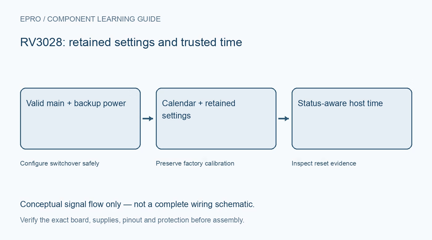
The RV-3028-C7 combines a clock circuit and crystal in a compact RTC module. Its low-power features are useful only when the surrounding board and configuration support them. Verify the exact part, backup arrangement and retained settings before selecting it for a battery-powered low-voltage project.
Identify the integrated module and carrier
The clock module contains an embedded crystal, but a breakout can add regulators, indicators and pull-ups that dominate system current. Read the carrier schematic and distinguish the module specification from complete-board consumption. A low typical chip current is not a measured battery-life promise for an assembled product.
Separate timekeeping from active-interface limits
The documented timekeeping and active I2C voltage ranges are not identical. Check the manual for the intended temperature, supply and access mode. Verify host pull-up levels and behavior when one side is unpowered rather than relying on a single minimum-voltage figure from a product summary.
Configure backup switchover deliberately
The factory-delivery configuration disables backup switchover. Choose the documented direct or level switching arrangement for the actual supplies and source. A connected backup battery does not prove switchover is enabled, and the backup pin must not simply be left floating when the feature is unused.
Keep charging separate from time retention
The device includes a configurable trickle charger, disabled by default. Do not enable it for a non-rechargeable battery. Check the actual carrier circuitry and backup-source specification before choosing any charging path or resistance; software convenience must not override cell chemistry and safe charging requirements.
Distinguish live settings from EEPROM
Configuration registers have EEPROM-related update and refresh behavior. A live setting can differ from what will return after a complete power cycle. Follow the manual’s busy checks and access sequence, preserve reserved and factory-calibration values, and avoid unnecessary repeated nonvolatile updates in a polling loop.
Use reset evidence to assess time integrity
The power-on-reset flag indicates that supply conditions may have corrupted time information. Preserve that evidence before clearing it and initialize trusted time when required. Calendar and UNIX-time functions also need an explicit software convention; the device does not automatically infer the user’s timezone or correct host policy errors.
Newest in the store


Verify the whole intended operating cycle
Test advancing time, intended backup transitions and restored configuration before relying on retention. Measure actual board current if battery life matters, with a suitable instrument and setup. Factory calibration conditions do not establish all-temperature accuracy, independent calibration or indefinite retention for an untested assembly.
Frequently asked questions
Does fitting a battery automatically enable backup?
No. The documented factory configuration has switchover disabled; verify the chosen retained settings.
May the trickle charger charge a normal primary coin cell?
Do not enable charging for a non-rechargeable source. Verify chemistry and the complete board circuit first.
Availability and illustration note
No matching Epro product was returned by the catalog search on 21 October 2026 UTC. This learning guide does not assert stock, a selling price or compatibility of an unidentified substitute. The illustration is an original conceptual signal-flow diagram, not a product photograph or complete wiring schematic.
Related Epro reading
For a first bench setup, review breadboard connections and continuity checks and I2C voltage-level translation. These guides do not replace the exact module schematic.
Technical references and limitations
Source: Micro Crystal RV-3028-C7 application manual. Electrical limits apply to the named part, not automatically to every carrier board. This is a documentation-based learning workflow, not a claim of independent hardware testing, traceable calibration or safety certification.