


TPS62135 Buck Converter: 7 Checks for VSEL, Modes and Recovery

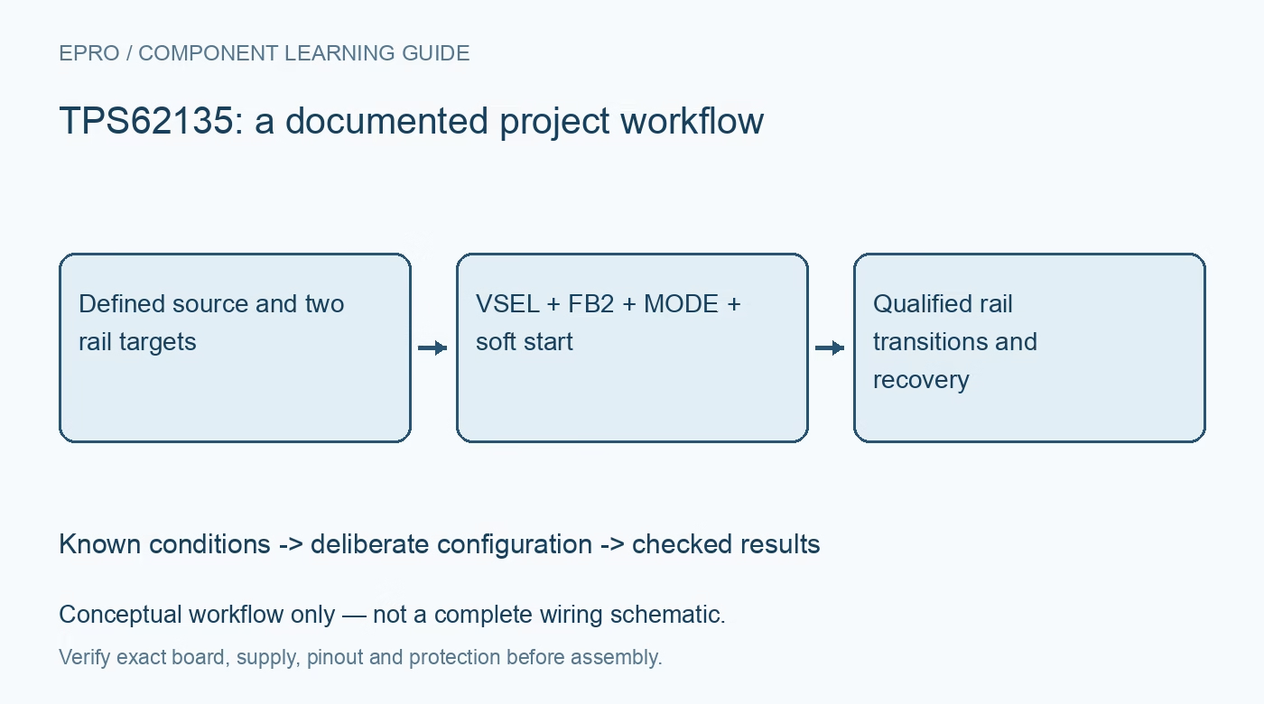
TPS62135 Buck Converter: 7 Checks for VSEL, Modes and Recovery
Design a TPS62135 buck rail with seven checks for VSEL and FB2, forced PWM, power-save accuracy, startup tracking, output discharge and hiccup recovery. This is a documentation-based planning guide, not a report of independent hands-on testing.
1. Identify TPS62135 versus TPS621351
The shared documentation covers two closely related buck converters with different discharge and fault behavior. TPS62135 includes active output discharge and hiccup overcurrent handling; TPS621351 does not have the same combination. Confirm the full ordering code before using a shutdown or short-circuit assumption in system logic. The family supports a 3 V to 17 V input and a 4 A class output, but the actual thermal, component and input-output conditions must still be satisfied. Manufacturer documentation.
2. Size the power stage for both target voltages
Select the inductor, effective output capacitance and input network for every intended operating state, including any second output setpoint. Check saturation, ripple, bias derating and load-step energy using the manufacturer design guidance. Nominal ceramic capacitance is not the effective capacitance under operating bias. Keep the high-current switching loop compact and route feedback away from it. A circuit that is stable at one voltage and one load is not automatically qualified after a dynamic setpoint change. Manufacturer documentation.
3. Use VSEL and FB2 as a divider-switch function
The nominal feedback reference is 0.7 V, while the documented adjustable output minimum is 0.8 V because the topology requires a divider. VSEL can enable an additional resistor path through FB2 to change the divider ratio and increase the output. This is not the fixed five-percent margining function of another converter. Calculate both resistor-network states and their tolerances, then check the downstream voltage limits before allowing the control signal to change. Manufacturer documentation.
4. Distinguish forced PWM from power-save operation
MODE high selects forced PWM, while MODE low permits PWM/PFM operation and automatic efficiency enhancement. These choices affect light-load ripple, switching activity and efficiency. The headline one-percent output accuracy is associated with the specified PWM conditions; do not extend it unchanged to all power-save situations. Check the electrical table and effective capacitance requirements for the actual output voltage. Define the observation bandwidth when comparing ripple, since different acquisition settings can make the same waveform appear very different. Manufacturer documentation.
Newest in the store


5. Review soft start and tracking with the real sequence
SS/TR supports a controlled startup ramp and tracking as documented. Select the capacitor or tracking arrangement for the allowed inrush, output capacitance and downstream sequencing. Review pre-biased and restart cases rather than measuring only a zero-volt cold start. Capture EN, SS/TR, output and PG together under a bounded load. A tracking relationship can have different error conditions from ordinary regulation, so the static output-accuracy headline is not a substitute for reviewing tracking specifications. Manufacturer documentation.
6. Treat discharge and hiccup as conditional circuit behavior
For TPS62135, shutdown discharge changes how stored output energy is removed, and hiccup protection changes how a sustained overcurrent condition is retried. Neither feature makes the rail safe under every externally back-powered or faulted connection. Review the exact conditions and timing in the functional-mode sections. Do not depend on repeated protection cycling as routine load-current control. Confirm that downstream devices tolerate the actual restart pattern and that another source cannot unintentionally fight the discharge path. Manufacturer documentation.
7. Validate setpoint changes and recovery separately
Test each voltage target, mode and representative load before combining them into transitions. Record overshoot, undershoot, settling, ripple, PG behavior and temperature with the installed LC network. Exercise only protected, bounded fault cases appropriate to the hardware, and compare the observed restart with the exact device variant. Preserve the configuration and test conditions with the results. A correct unloaded output voltage does not qualify dynamic voltage switching, heavy-load thermals or safe recovery from a persistent short. Manufacturer documentation.
Related reading: TPS62150 Buck Converter: 7 Checks for Margining and Tracking.
Catalog note: The exact-part search did not return a matching Epro listing during preparation. Check the current catalog; this guide makes no price, availability or included-accessory claim.