


TCA6416A GPIO Expander: 7 Checks for Dual-Rail Sequencing

TCA6416A GPIO Expander: 7 Checks for Dual-Rail Sequencing
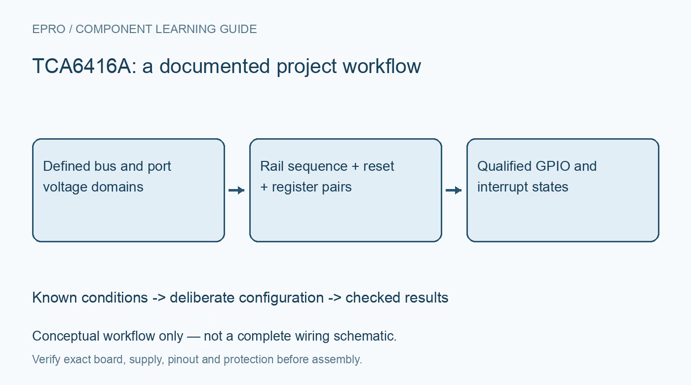
Configure TCA6416A GPIO with seven checks for VCCI and VCCP, supply sequencing, paired registers, reset recovery, port biasing and interrupt servicing. This is a documentation-based planning guide, not a report of independent hands-on testing.
1. Draw the two voltage domains separately
TCA6416A has VCCI for the communication-side supply and VCCP for the port-side supply. Both support the documented 1.65 V to 5.5 V range, enabling GPIO expansion across different logic domains. Draw each pull-up and external load against its intended rail rather than treating both supplies as one generic VCC. Check host thresholds, port output levels and pin ratings. Voltage translation inside an expander is not the same as an unrestricted bidirectional translator placed in every external signal path. Manufacturer documentation.
2. Review the recommended supply sequence
The datasheet recommends ramping VCCP before VCCI to avoid the possibility of SDA becoming stuck low. Check this on the actual board, including brownouts and re-ramping, rather than validating only the first power-on from a laboratory supply. The power-on reset is tied to the documented supply behavior and has specified ramp conditions. Two rails reaching their correct final voltages does not prove that their startup sequence was valid or that the bus state machine initialized correctly. Manufacturer documentation.
3. Use RESET as a controlled initialization input
The active-low RESET input restores the registers and communication state machine without requiring the port rail to be powered down. Meet its pulse timing and provide a suitable defined high level when it is not actively driven. Reset makes the GPIO pins inputs, so external equipment must remain safe during that interval. Reapply reviewed output-latch values before changing direction masks. A recovery routine that restores communication but unintentionally releases a subsystem enable is not a complete system recovery. Manufacturer documentation.
4. Respect the four paired-register groups
Input, output, polarity and configuration registers are arranged in two-port pairs. A continued transaction alternates between the two registers in the selected pair rather than walking freely through the whole map. Use explicit command bytes and test with asymmetric port patterns. Keep output-latch readback distinct from an input observation of the physical pin. A successful write proves communication and register acceptance, not that an external LED, reset line or actuator reached the required electrical state. Manufacturer documentation.
Newest in the store




5. Provide deliberate input bias and load limits
Review the port-pin structure and provide external bias where a disconnected input needs a defined state. Do not borrow the internal weak pull-up assumptions of another expander. For LED or control loads, check individual-pin and aggregate current limits and add external current limiting. Evaluate leakage and threshold margins across both voltage domains. A pin described as voltage tolerant still has specific conditions; it should not be treated as a general-purpose connection to any powered subsystem. Manufacturer documentation.
6. Match interrupt pull-up and service policy to the host
INT is open drain and must be pulled to a suitable voltage for the device receiving it, within the documented limits. Reading the input port responsible for the change resets the relevant interrupt comparison; merely writing an output register is not a universal clear. Service both ports as required and recheck INT for changes arriving during the read. Sequential port bytes are not a simultaneous sixteen-bit snapshot, and this interface does not retain a complete timestamped edge history. Manufacturer documentation.
7. Test sequencing, reset and interrupt recovery together
Capture VCCP, VCCI, RESET and bus behavior through normal startup and the brownout cases the system can encounter. Verify pin directions and output latches after each recovery before enabling external equipment. Then exercise changes on both input ports and confirm interrupt clearing. Retain rail ordering, pull-up connections and register masks with the test record. A clean bus scan after steady-state power application is useful evidence, but it cannot qualify the more difficult dual-rail startup and restart cases. Manufacturer documentation.
Related reading: TCA9555 GPIO Expander: 7 Checks for Paired Ports and Interrupts.
Catalog note: The exact-part search did not return a matching Epro listing during preparation. Check the current catalog; this guide makes no price, availability or included-accessory claim.