


TPS62827 Buck Converter: 7 Checks for PSM and Power Good

TPS62827 Buck Converter: 7 Checks for PSM and Power Good
Plan TPS62827 rails with seven checks for the A suffix, feedback network, light-load PSM, dropout, active discharge and power-good timing. This is a documentation-based planning guide, not a report of independent hands-on testing.
1. Distinguish TPS62827 from the forced-PWM A version
The family offers adjustable and fixed-output devices with different current ratings. TPS62827 is the adjustable 4-A member that automatically uses power-save operation at light load; TPS62827A is the forced-PWM version. There is no generic MODE pin to invent from another converter. Check the full order code against the device-options table and schematic. A board sold under a family name must not be assumed to have the same light-load spectrum or quiescent behavior as a different suffix. Manufacturer documentation.
2. Keep the complete operating envelope inside the ratings
The recommended input range is 2.4 V to 5.5 V, and the adjustable output range is 0.6 V to 4 V. This is a buck converter, not a way to obtain a regulated rail above the input. The 4-A designation remains conditional on thermal design, component selection and operating point. Start with a current-limited low-voltage supply and modest dummy load; check connector and trace capacity before increasing the load toward the intended application requirement. Manufacturer documentation.
3. Design feedback and compensation as one network
The adjustable output follows VOUT = 0.6 V multiplied by one plus the upper-to-lower divider ratio. The datasheet recommends a lower divider resistor no higher than 100 kilohms and specifies a feedforward-capacitor calculation, with 120 pF used for a 100-kilohm lower resistor. Treat these as part of the documented design, not arbitrary optional parts. Verify tolerances, leakage, placement and the recommended inductor/capacitor combinations. Fixed-output relatives use a different feedback connection and cannot be copied indiscriminately. Manufacturer documentation.
4. Expect PSM frequency and voltage to change at light load
At light load the non-A device reduces switching frequency to maintain efficiency. The datasheet also notes a slight rise of output voltage above the nominal target in power-save mode. A no-load measurement therefore does not establish loaded accuracy, ripple or interference. Capture light-load and heavier-load behavior with the same probe technique, and record whether the converter is in PSM or PWM. Choose the forced-PWM variant only after reviewing its different efficiency and operating trade-offs. Manufacturer documentation.
Newest in the store


5. Include dropout and startup in the load budget
Near the input voltage, the converter can enter 100-percent duty operation. Output then falls below input by conduction losses in the high-side switch and inductor; this is not lossless regulation at any load. The internal startup sequence begins about 250 microseconds after enable and includes a controlled ramp. Measure the actual rail under the weakest intended source and largest permitted load step. A prebiased-output capability does not remove the need to evaluate interaction with another powered rail. Manufacturer documentation.
6. Interpret power good and discharge with their conditions
PG is an open-drain output with a window comparator, not a precision measurement of the rail. It is low when disabled, in undervoltage lockout or thermal shutdown, and has documented blanking and deglitch delays. Its pull-up rail must remain below 5.5 V and satisfy the receiving logic. Active output discharge acts through the switch node during shutdown and requires VIN to remain present. Removing all input power is therefore not equivalent to a commanded, powered shutdown. Manufacturer documentation.
7. Qualify regulation before connecting sensitive electronics
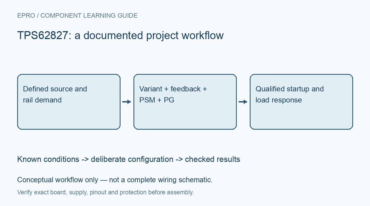
Use the manufacturer layout guidance, short switching loops, local input bypassing and a quiet feedback route. Test startup, enable-off discharge, low-input dropout, light-load ripple and representative dynamic loads using noncritical dummy loads first. Hiccup protection is a fault response, not permission to operate permanently into overload. Record source impedance, effective capacitor values, inductor rating and temperature rise with the waveforms. Only connect the final processor or sensor after its voltage and sequencing limits are satisfied. Manufacturer documentation.
Related reading: TPS62840 Buck Converter: 7 Checks for a Low-Power Rail.
Catalog note: The exact-part search did not return a matching Epro listing during preparation. Check the current catalog; this guide makes no price, availability or included-accessory claim.