


TSL2591 Light Sensor: 7 Dynamic-Range and Optical Checks

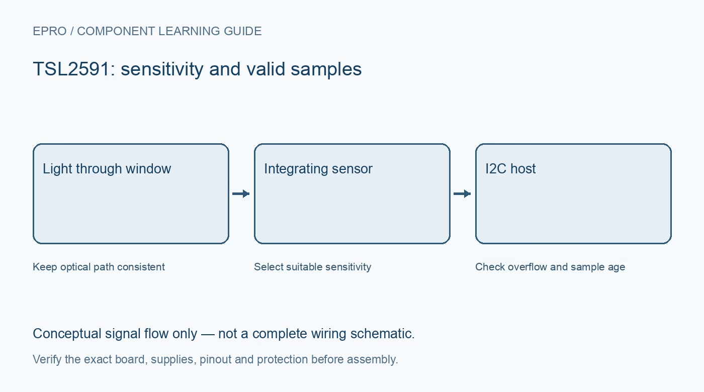
A TSL2591 offers high sensitivity and a wide configurable dynamic range, but these are system capabilities rather than a promise that one fixed setting measures every scene correctly. Choose the board, optical path and software strategy together.
Understand the two photodiode channels
The device combines a broadband visible-plus-infrared channel with an infrared-responsive channel. Software uses both to estimate illuminance. Counts depend on integration and gain; they are not automatically lux, optical watts or a universal measure of plant-growing light.
Check the exact interface variant and carrier
Verify the sensor designation, supply requirements and allowed bus voltage from its documentation. A module may add regulation or level translation, but do not infer either from connector shape. Pay attention to the ordered variant because interface electrical details are not identical for every family option.
Plan address sharing before assembly
The primary I2C address is 0x29. The documented secondary 0x28 access path is for reading registers and is not a second independently selectable sensor address. Do not plan two colliding modules on one bus by treating that read path as an address jumper.
Choose gain and timing as a pair
Configurable gain and integration determine low-light response, latency and bright-light headroom. High sensitivity can saturate under ordinary bright scenes. Select a strategy that changes configuration deliberately, waits for a valid new integration and records which setting produced each observation.
Account for the final optical window
The datasheet discusses operation behind dark glass, but the window still changes spectral transmission and geometry. A lux estimate depends on those conditions. Measure through the intended cover and keep the sensor opening clear of adhesive, dust and obstructions rather than calibrating an uncovered board and later enclosing it arbitrarily.
Distinguish useful trends from absolute metrology
Display dimming and day/night decisions may work with relative thresholds. A formal illuminance survey needs a suitable calibrated instrument and measurement procedure. Very low indicated lux or many decimal places do not establish traceable accuracy, angular response or suitability for a regulatory report.
Newest in the store


Require explicit invalid and over-range states
Inspect how the intended library reports saturation, short reads and initialization failure. Keep successful-sample time and active configuration in the application. An unavailable sensor must not be presented as complete darkness, especially if lighting decisions depend on the reading.
Frequently asked questions
Can I use address 0x28 to add a second sensor beside one at 0x29?
No. The documented secondary read-access mechanism does not make a second colliding device independently addressable.
Does the largest gain always yield the most useful measurement?
No. It may saturate. Gain must suit the scene, integration time and application response requirements.
Availability and illustration note
No matching Epro product was returned by the catalog search on 19 October 2026. This learning guide does not assert stock, a selling price or compatibility of an unidentified substitute. The illustration is an original conceptual signal-flow diagram, not a product photograph or complete wiring schematic.
Related Epro reading
For a first bench setup, review breadboard connections and continuity checks and I2C voltage-level translation. These guides do not replace the exact module schematic.
Technical references and limitations
Source: ams OSRAM TSL2591 datasheet. Electrical limits apply to the named part, not automatically to every carrier board. This is a documentation-based learning workflow, not a claim of independent hardware testing, traceable calibration or safety certification.