


TXU0104 Logic Translator: 7 Checks for Fixed Direction and OE

TXU0104 Logic Translator: 7 Checks for Fixed Direction and OE
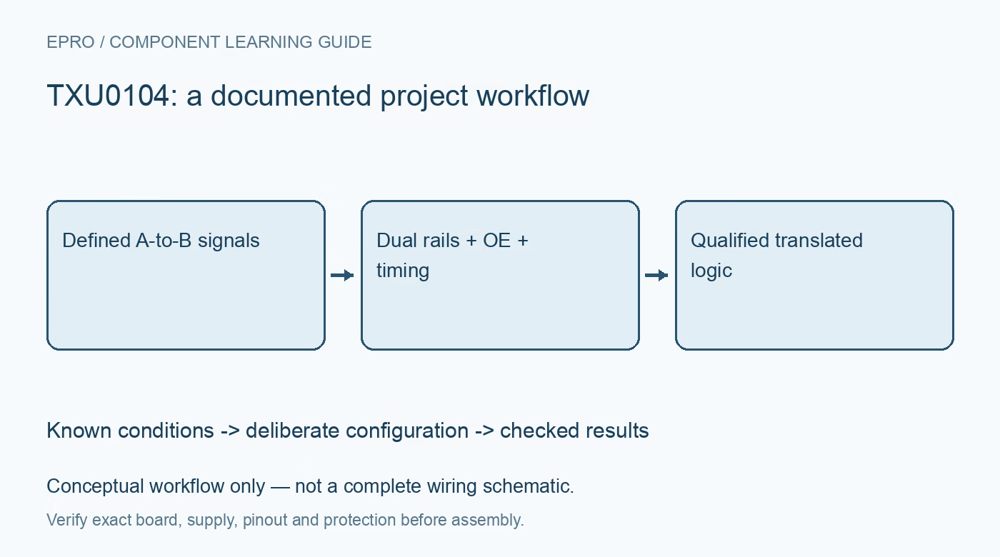
Plan a TXU0104 interface by checking A-to-B direction, OE polarity, dual supplies, startup isolation and timing before enabling connected logic. This is a documentation-based planning guide, not a report of independent hands-on testing.
1. Identify the exact translator and package
Start with the complete orderable part, package drawing and board schematic. TXU0104 has four A inputs and four B outputs: its channels translate from A to B, not automatically in whichever direction a peripheral happens to talk. Shared family descriptions are not a substitute for the pin-function table. A connector-compatible footprint also does not establish functional equivalence with an automatic-direction translator. Label every channel source and destination before connecting the two boards. Manufacturer documentation.
2. Assign both supply domains explicitly
The A port follows VCCA and the B port follows VCCB. The specified operating supply range for each rail is 1.1 V to 5.5 V, but this does not authorize any signal voltage at any pin under every power state. Check recommended input levels, absolute limits and ground references for the actual rail pair. Add the recommended local decoupling and measure both rails at the device, rather than relying only on upstream regulator settings. Manufacturer documentation.
3. Keep TXU0104 and TXUN0104 enable polarity separate
TXU0104 uses active-high OE; TXUN0104 uses active-low output enable. Copying a pull resistor from the other variant can therefore enable the outputs when isolation was intended. The control circuitry permits enable referencing to either supply, subject to the documented thresholds. For TXU0104, an external pull-down provides an explicit disabled startup state. Verify the host reset state and resistor network together, including what happens when the host pin becomes high impedance. Manufacturer documentation.
4. Design around fixed push-pull direction
Use this translator for signal paths whose direction is already established. An interface with a return-data signal needs an appropriately directed return path; turning OE off does not reverse a TXU0104 channel. Likewise, a shared open-drain I2C connection is not equivalent to four fixed-direction push-pull channels. Review every peripheral output and pull resistor for contention. During initial qualification, hold downstream functions inactive until channel ownership and idle levels have been confirmed. Manufacturer documentation.
Newest in the store


5. Qualify disabled and partial-power states
The datasheet describes supply isolation when either rail is below 100 mV or disconnected while the other supply is within recommended conditions. Read those conditions alongside the partial-power-down specifications; do not expand them into a promise that arbitrary external voltages are harmless. Exercise normal rail sequencing with current-limited supplies and observe whether downstream inputs remain controlled. High impedance does not define a logic value, so a receiving circuit may still need a deliberate idle-state resistor. Manufacturer documentation.
6. Budget timing at the actual load
Propagation delay, edge behavior and achievable switching rate depend on the selected supply pair and load. Use the applicable switching tables and test conditions, not a single headline rate for every installation. Include trace capacitance, connector loading and receiver thresholds in the budget. Observe representative signals at the receiving pin with suitable probing. A clean-looking unloaded output is not evidence that the longest cable, largest fanout or fastest operating mode has passed. Manufacturer documentation.
7. Record evidence before releasing the interface
Create a channel map, rail table, enable truth table and startup sequence for the assembled design. Record observed idle levels, representative timing and the expected behavior during a normal host reset. Keep input ownership separate from output-enable state in firmware documentation. This establishes a repeatable interface qualification, not certification or a hands-on result from this guide. If any signal needs bidirectional ownership, select a suitable topology before proceeding rather than attempting to fix direction in software. Manufacturer documentation.
Related reading: SN74LVC1T45 Translator: 7 Checks for Direction and Power States.
Catalog note: The exact-part search did not return a matching Epro listing during preparation. Check the current catalog; this guide makes no price, availability or included-accessory claim.