


ULN2803 Circuit Example: Test One LED Before Adding Loads

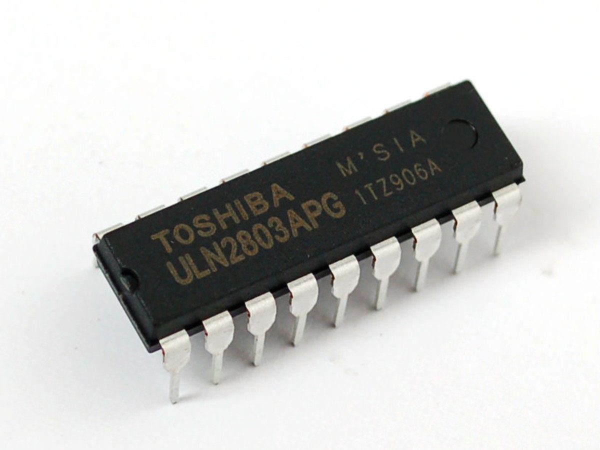
This ULN2803 circuit example starts with one resistor-limited LED to check channel mapping and sink behavior. It intentionally avoids a relay or motor so a wiring mistake is easier to diagnose. Use a documented compatible logic source and a verified ULN2803A package, not an assumed pin map from a different array.
Check the return and one channel pair

With power removed, connect the common-emitter pin to the circuit return. Identify input one and its matching output from the actual eighteen-pin drawing; the physical output order is reversed across the package. Use the manufacturer pin functions rather than assuming pin 1 connects to the pin directly opposite by number.
Build a small resistive LED load
Connect the supported positive load supply through a 2.2 kohm resistor and a correctly oriented indicator LED to the selected output collector. This deliberately small load is useful for a first functional check. The Darlington on-state drop reduces available LED voltage, so use the actual measured resistor drop to estimate current rather than promising one exact brightness.
Drive the input from a supported source
Use a logic source compatible with the array’s documented input-current and threshold conditions. A five-volt TTL/CMOS-compatible example matches the referenced ULN2803A family intent, but the actual source capability still matters. Keep untested inputs at defined inactive levels so they do not accidentally enable attached circuits.
Understand what happens at the collector
When the input is inactive, the output does not source a positive voltage; the external load path determines its level. When the channel conducts, it sinks current through the emitter return and the LED should light. This is not a current-regulated LED driver. Keep the series resistor in place even if the output appears to limit current in a faulty setup.
Treat COM separately from logic power
There is no conventional VCC pin for powering the Darlington logic like a shift register. COM serves the internal suppression-diode network. A purely resistive LED test does not need to use it as a flyback path, but its connection must remain consistent with the complete circuit. Do not tie it to ground simply because it is called common.
Measure before expanding to more channels
Check LED current, the selected output’s voltage drop and the inactive state. Repeat on another channel only after confirming the map. Several small LEDs establish basic wiring, not an eight-channel high-current capability. Recalculate total dissipation and supply/trace currents before adding larger loads or a higher simultaneous duty cycle.
Newest in the store


Redesign protection for inductive loads
For a supported coil circuit, provide the correct clamp path through COM and the appropriate load supply, while checking all diode and output limits. A harmless LED result does not validate relay-coil current, release timing or external transients. Keep this learning example separate from any machine or safety function.
Relevant Epro listing
Product information and prices were checked on 19 October 2026. This is a current snapshot, not a historical price associated with the publication timestamp. Stock, accessories and checkout prices can change. Listing claims are not independent performance or authenticity certifications.
| Product | Checked price | Stock |
|---|---|---|
| ULN2803 IC in Pakistan | PKR 50 | In stock |
Frequently asked questions
Why does the output not provide five volts by itself?
It is a sink driver, not a high-side voltage source. The external supply and load complete the circuit.
Can I remove the LED resistor?
No. The channel is not a regulated constant-current LED output; use an appropriate load resistor.
Related Epro reading
Review breadboard connections before assembling a prototype. For controller expansion, the Mega 2560 pin guide explains why pin names and electrical limits must be checked together.
Technical references and test limitations
This guide uses the documentation linked below. The procedures are for a controlled, low-voltage learning setup; no independent hands-on test of the particular seller board is claimed. Record the actual part markings, wiring and firmware version before drawing conclusions from a test.