


24V to 12V Buck Converter: 7 Load-Sizing Checks

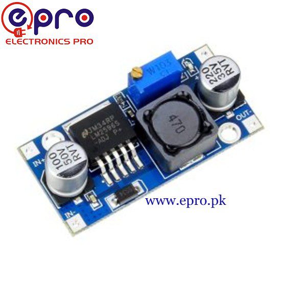
Last checked: 18 October 2026. Any prices below are dated Epro listing examples, not guaranteed current quotations. Confirm the exact model, stock and package before ordering.
A 24V to 12V buck converter can power a suitable 12V DC load from a higher-voltage DC source. The important word is “suitable”: a board that runs a small controller may not safely start a motor, support a long LED strip or survive a vehicle’s electrical transients.

This guide focuses on low-voltage DC planning. A converter is not an AC mains adapter, and a hobby board is not automatically approved for vehicle, industrial or safety-critical installation. Use the exact module documentation and obtain qualified assistance when the application demands it.
1. Check the real input range of a 24V to 12V buck converter
A nominal 24V source may be a regulated supply or a battery system with a changing voltage. Check its minimum and maximum operating voltage, including charging conditions where relevant. Also consider whether switching equipment creates transients beyond the steady-state value. The converter’s absolute maximum is not a recommended everyday design target.
A basic step-down circuit needs enough input headroom to regulate its output. If the source can fall close to or below 12V, a buck-only module may stop maintaining the required voltage. See the buck-boost selection guide when the source crosses the desired output level.
2. Write down the load current and power
For a 12V load drawing 1A, output power is 12W. If a worked example assumes 90% efficiency, the input power is about 13.3W and input current from a steady 24V source is about 0.56A. This arithmetic illustrates the relationship; it is not a measured efficiency claim for a listed module.
Include every device sharing the output. LEDs, control boards and accessory fans all contribute. Do not size a converter from only the controller’s idle consumption when a connected load draws much more.
3. Allow for startup and stall conditions
Motors and some lamps can draw a larger current at startup than during normal operation. A stalled motor may remain at a high current and overheat. Check the load manufacturer’s requirements and the converter’s transient response. A steady-state calculation alone cannot establish reliable motor starting.
4. Separate regulator specifications from board capability
The Texas Instruments LM2596 reference describes the IC’s electrical capabilities, but an assembled module also depends on its inductor, diode, capacitor ratings and thermal layout. An advertised maximum current is not a promise of continuous operation inside a hot enclosure.Newest in the store


Epro’s LM2596 step-down module — PKR 180 and XL4015 module — PKR 280 are listing examples, not a statement that either suits every 12V load. Match the precise board and its documentation to the application before purchase.
5. Plan wiring, fusing and mounting
Choose wire and connectors for the actual current, length and environment. A long thin cable can create a meaningful voltage drop at the load. Do not route a high-current output through a solderless breadboard. Insulate the underside of exposed modules and provide strain relief so a pulled cable cannot loosen a live terminal.
A battery can supply substantial fault current even at low voltage. Protection should suit the source, wiring and load. Do not choose a fuse value merely by copying the largest number printed on the converter.
6. Set and test the output before final connection
Disconnect the final device, apply a suitable controlled input and adjust the output while measuring DC voltage. Then test under an appropriately rated safe load. Verify voltage at the load end of the cable and observe startup behavior. The LM2596 setup guide explains common measurement mistakes.
7. Check temperature under realistic conditions
Test with the expected enclosure and airflow, not only on an open bench. Monitor the regulator, diode, inductor, terminals and nearby wiring. Excessive heat, unstable output or repeated shutdown means the setup needs correction or a more suitable converter. Do not defeat thermal protection.
Frequently asked questions
Can a 24V to 12V buck converter charge a battery?
Voltage reduction alone does not provide the correct charging profile, current control or battery protections. Use a charger designed for the battery chemistry.
Does it isolate the two circuits?
A common non-isolated buck module does not. Confirm the topology rather than assuming separate terminals mean isolation.