


2N2222 as a Switch: A Resistor-Limited LED Bench Test

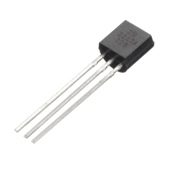
Using a 2N2222 as a switch is easiest to learn with a low-current LED, not a motor or relay. This example describes a low-side NPN circuit by pin function because the lead order must be confirmed for the actual supplied variant. It is a controlled five-volt learning test, not a general power-driver design.
Identify the transistor before wiring

Match the full part marking and package to a manufacturer drawing. Locate base, collector and emitter explicitly and disconnect power while inserting it. Do not use a universal left-to-right pin order copied from a different 2N2222-family part. Begin with a current-limited supply and an inspected breadboard.
Build the resistor-limited load path
Connect the verified emitter to ground. Connect five volts through a 1 kohm resistor and a correctly oriented LED to the collector. The exact resistor/LED ordering within that series path is not important, but both must be in the load path. Use a small indicator LED, not an unresisted high-power LED module.
Add a limited base drive and off-state default
Feed the verified base from a suitable five-volt logic output through 4.7 kohm, with a separate 100 kohm base-to-emitter resistor to help hold it off when the source is inactive. These are conservative illustrative learning values for this small LED load. Verify the actual host’s output capability and do not apply them blindly to another load.
Understand the illustrative currents
If LED drop is assumed near 2 V and collector drop near 0.2 V, the 1 kohm load resistor gives about 2.8 mA. With an assumed 0.8 V base-emitter drop, 4.7 kohm from five volts gives about 0.89 mA base current. These are calculations from stated assumptions, not measurements or guaranteed values for every device.
Test low and high control states
Drive the control low and confirm the LED is off, then high and observe it turn on. Measure the load-resistor voltage to estimate actual LED current and measure collector-to-emitter voltage with the correct reference. Turn power off before moving leads. If the transistor becomes warm in this modest test, stop and inspect rather than accepting that as normal.
Diagnose without removing protection
If the LED never lights, check its polarity, breadboard continuity, common ground and the verified transistor lead roles. If it stays lit, check collector/emitter placement and the control state. Never remove the LED or base resistor to force a response. A meter’s gain reading is not a substitute for checking the loaded switching circuit.
Newest in the store


Do not scale directly to an inductive load
A relay or motor needs a separate current, base-drive, thermal and transient-protection design. A flyback path and startup/stall behavior may matter. A transistor that switches a few milliamps successfully is not automatically suitable for a large load. Use a properly specified driver when the application exceeds this learning example.
Relevant Epro listing
Product information and prices were checked on 19 October 2026. This is a current snapshot, not a historical price associated with the publication timestamp. Stock, accessories and checkout prices can change. Listing claims are not independent performance or authenticity certifications.
| Product | Checked price | Stock |
|---|---|---|
| 2N2222 NPN Transistor | PKR 5 | In stock |
Frequently asked questions
Can I connect the base directly to a GPIO?
Use a correctly selected base resistor. The GPIO and transistor limits both matter.
Does a working LED test prove a relay driver is safe?
No. A relay requires a separate load-current, drive, thermal and inductive-protection design.
Related Epro reading
Review breadboard connections before assembling a prototype. For controller expansion, the Mega 2560 pin guide explains why pin names and electrical limits must be checked together.
Technical references and test limitations
This guide uses the documentation linked below. The procedures are for a controlled, low-voltage learning setup; no independent hands-on test of the particular seller board is claimed. Record the actual part markings, wiring and firmware version before drawing conclusions from a test.