


PC817 Optocoupler: Pinout, CTR and Low-Voltage Selection

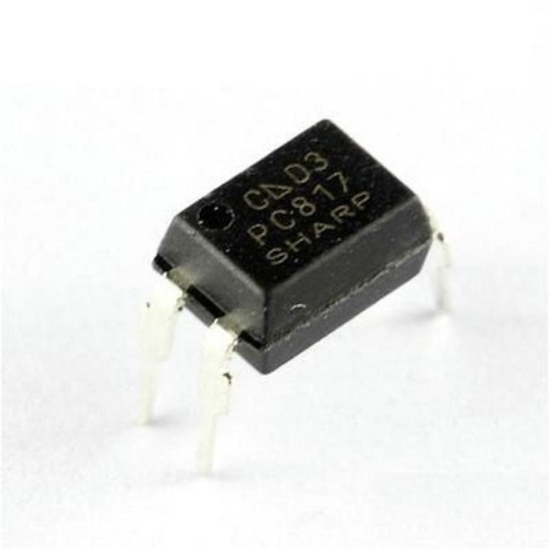
A PC817 optocoupler contains an infrared LED and a phototransistor coupled through light. It can transfer a signal between circuits without a direct conductive signal path when the entire system preserves the isolation boundary. Select it by the exact variant, input current, current-transfer ratio and required switching behavior.
Check the actual manufacturer and grade

PC817 is sold by different suppliers with grade and suffix differences. The linked Sharp datasheet documents one specific family, not an authenticity certification for an unmarked seller part. Identify the supplied package and use its appropriate specification. A generic listing name alone does not establish every voltage, timing or safety approval.
Identify the four pins correctly
For the documented common DIP pinout, pin 1 is LED anode, pin 2 cathode, pin 3 transistor emitter and pin 4 collector. Verify notch/dot orientation and the package drawing. The input LED needs correct polarity and current limiting; the output transistor is not simply a second LED or a voltage-generating source.
Choose input current with a resistor
Do not connect the LED directly across a GPIO or supply. Select a series resistor from the available drive voltage, LED forward-voltage range and intended current, while respecting the host output capability and device ratings. A resistor calculated from only a typical LED voltage may need tolerance analysis for a real design.
Use worst-case current-transfer information
CTR relates collector current to LED input current under stated conditions. It varies with grade, current, temperature and device spread. A typical percentage is not a guaranteed universal gain. Size the output pull-up and input drive using the applicable minimum behavior and a suitable margin, then verify the intended logic levels.
Consider output inversion and speed
A common output circuit uses an emitter at its local ground and a collector pull-up to its local logic supply. LED current then tends to pull the collector low, so the logical action is inverted. Saturation, pull-up resistance and capacitance affect switching speed. The PC817 is not automatically suitable for a fast digital bus just because it is an optocoupler.
Preserve the boundary if isolation is required
Joining the two circuit grounds, or connecting a grounded USB cable or test instrument across them, can defeat the intended galvanic separation. Isolation also depends on PCB spacing, supplies, enclosure and the full system design. This article is limited to safe low-voltage learning circuits; it is not a mains-isolation construction guide.
Newest in the store


Define a modest functional check
Start with a current-limited LED input and a lightly loaded transistor output. Verify that output changes between the expected high and low states and measure the actual LED current. A successful switch does not validate safety certification or every CTR/timing corner. Keep consequential loads disconnected until the interface design is properly reviewed.
Relevant Epro listing
Product information and prices were checked on 19 October 2026. This is a current snapshot, not a historical price associated with the publication timestamp. Stock, accessories and checkout prices can change. Listing claims are not independent performance or authenticity certifications.
| Product | Checked price | Stock |
|---|---|---|
| PC817 Optocoupler | PKR 12 | In stock |
Frequently asked questions
Does the output create its own logic voltage?
No. The phototransistor needs an appropriate external output circuit, commonly a pull-up to the receiving side’s supply.
Does a PC817 automatically make a PCB mains-safe?
No. Safety depends on the complete approved design, layout, spacing, supplies and construction, not one component label.
Related Epro reading
Review breadboard connections before assembling a prototype. For controller expansion, the Mega 2560 pin guide explains why pin names and electrical limits must be checked together.
Technical references and test limitations
This guide uses the documentation linked below. The procedures are for a controlled, low-voltage learning setup; no independent hands-on test of the particular seller board is claimed. Record the actual part markings, wiring and firmware version before drawing conclusions from a test.