


74HC4067 Arduino: 7 Channel and ADC-Settling Checks

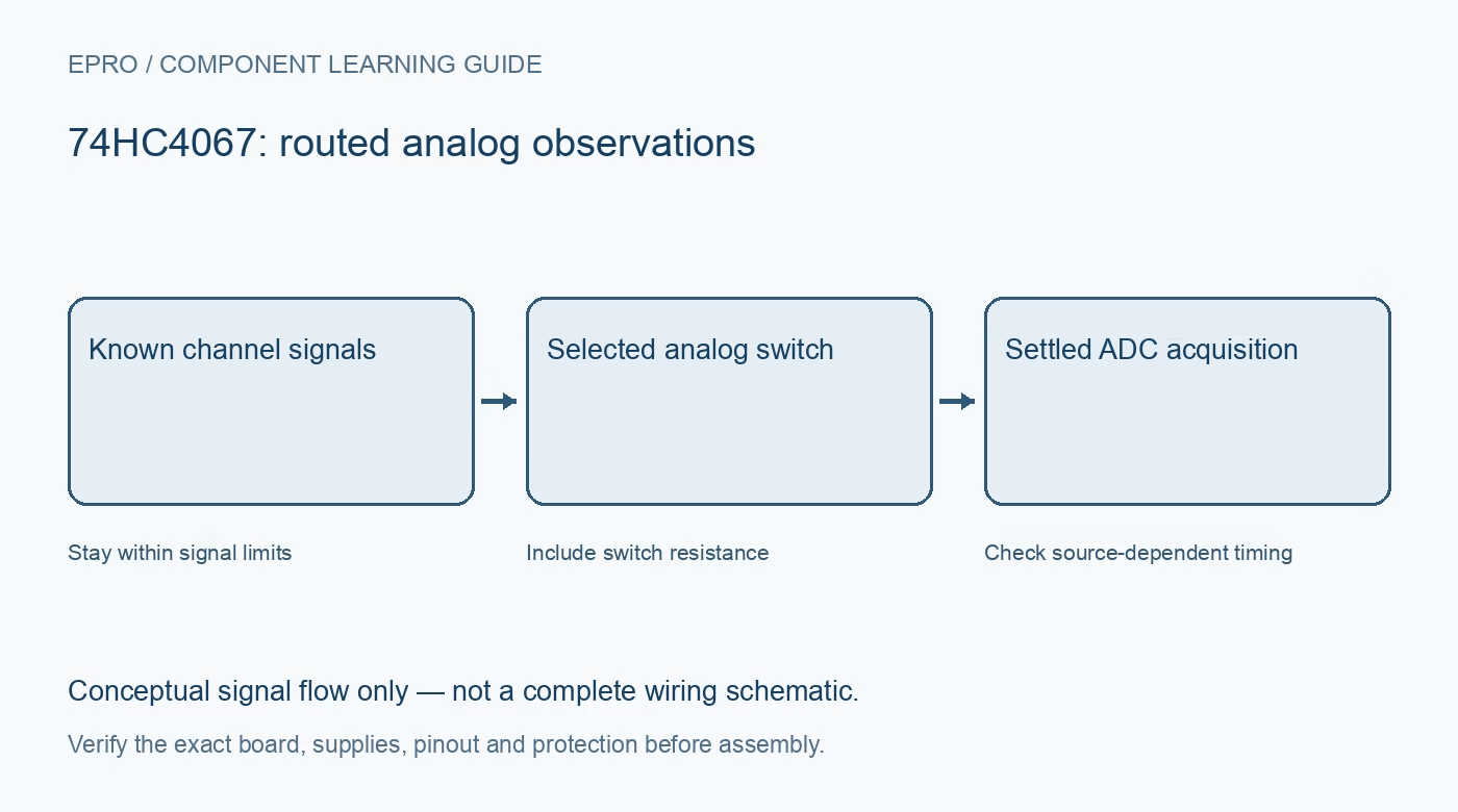
A 74HC4067 Arduino scanner should first prove which channel reaches the common terminal, then establish how long the ADC must acquire it. Avoid beginning with sixteen unknown sensors, because an address-order error and a settling error can otherwise look like the same fault.
Verify supplies and analog limits
Match the device and host voltage limits and inspect the actual module’s channel, common, select and enable labels. Use only known safe low-voltage sources for the first test. A 5 V-powered switch does not automatically protect a 3.3 V ADC from a selected 5 V signal.
Define enable before selecting channels
Hold enable high for a disconnected state while initializing select pins. Ensure the hardware has appropriate defined startup levels if the host resets. Remember that the common terminal can float while disabled; add only the biasing justified by the measurement design.
Verify binary channel order
Use the documented S0 through S3 significance rather than assuming physical connector order matches software bit order. Connect distinct known voltages to two channels and confirm the selection table slowly. Keep unused channels at defined safe levels when they will be sampled.
Avoid sampling during address transitions
Disable the switch where appropriate, update the select lines, then enable and allow the network to settle before acquisition. Separate writes to several GPIO pins are not necessarily simultaneous. The switch’s typical internal break-before-make action does not eliminate every host-controlled transition artifact.
Set acquisition time for the real source
Include sensor source resistance, switch resistance, wiring capacitance and the host ADC requirements. A discarded first conversion can help some systems, but is not a universal replacement for adequate settling. Validate the chosen delay and sampling sequence against the required error budget.
Look for history-dependent readings
Alternate between two known voltages and compare forward and reverse scan orders. If a channel depends on the previous selection, investigate charge sharing and acquisition time before applying a software offset. Keep raw counts, selected channel and timing in the diagnostic log.
Newest in the store


Validate disabled and recovery behaviour
Confirm that disabling the path stops the intentional connection without interpreting a floating ADC result as a genuine sensor value. Test a controlled host restart and restore a known channel. These checks demonstrate routing and acquisition behaviour, not galvanic isolation or certified measurement accuracy.
Frequently asked questions
Will one fixed tiny delay work for every sensor?
Not necessarily. Settling depends on the complete source, switch and ADC network.
Does a strange first conversion prove the chip is faulty?
No. Check channel ordering, retained charge and ADC acquisition requirements first.
Availability and illustration note
No matching Epro product was returned by the catalog search on 21 October 2026 UTC. This learning guide does not assert stock, a selling price or compatibility of an unidentified substitute. The illustration is an original conceptual signal-flow diagram, not a product photograph or complete wiring schematic.
Related Epro reading
For a first bench setup, review breadboard connections and continuity checks and I2C voltage-level translation. These guides do not replace the exact module schematic.
Technical references and limitations
Source: Nexperia 74HC4067/74HCT4067 datasheet. Electrical limits apply to the named part, not automatically to every carrier board. This is a documentation-based learning workflow, not a claim of independent hardware testing, traceable calibration or safety certification.